- 您現(xiàn)在的位置:買賣IC網(wǎng) > PDF目錄371435 > 28F020 (Intel Corp.) 5 V Bulk Erase Flash Memory(5V 整體擦寫閃速存儲器) PDF資料下載
參數(shù)資料
| 型號: | 28F020 |
| 廠商: | Intel Corp. |
| 英文描述: | 5 V Bulk Erase Flash Memory(5V 整體擦寫閃速存儲器) |
| 中文描述: | 5伏體擦除閃存(5V的整體擦寫閃速存儲器) |
| 文件頁數(shù): | 10/47頁 |
| 文件大小: | 758K |
| 代理商: | 28F020 |
第1頁第2頁第3頁第4頁第5頁第6頁第7頁第8頁第9頁當前第10頁第11頁第12頁第13頁第14頁第15頁第16頁第17頁第18頁第19頁第20頁第21頁第22頁第23頁第24頁第25頁第26頁第27頁第28頁第29頁第30頁第31頁第32頁第33頁第34頁第35頁第36頁第37頁第38頁第39頁第40頁第41頁第42頁第43頁第44頁第45頁第46頁第47頁

28F010/28F020
E
10
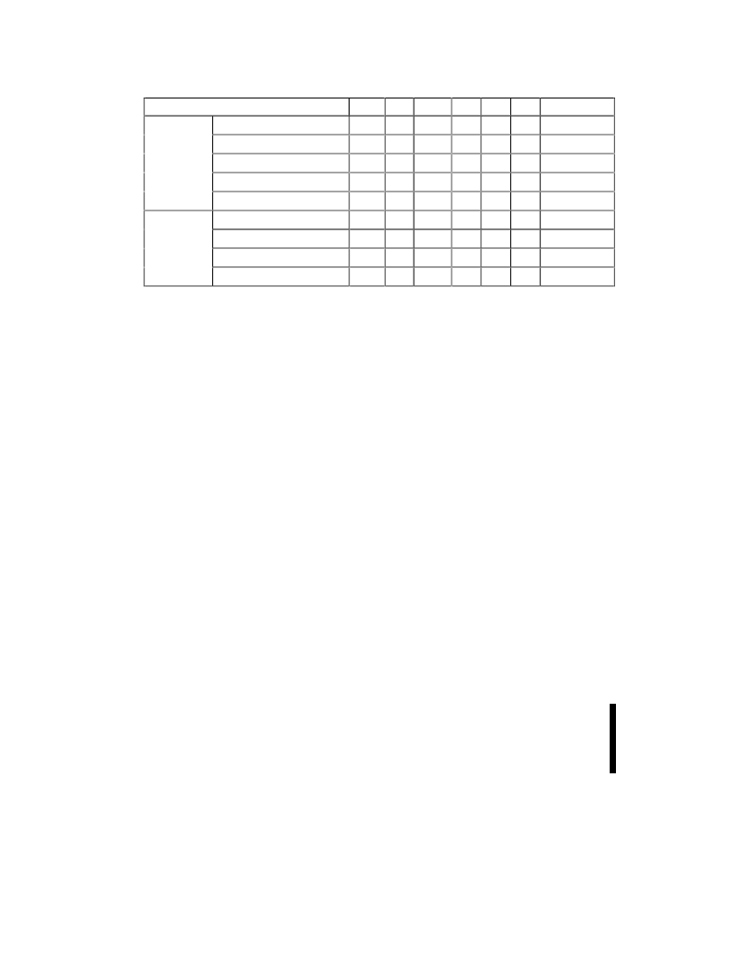
Table 2. 28F010/28F020 Bus Operations
Mode
V
PP(1)
A
0
A
9
CE#
OE#
WE#
DQ
0
–DQ
7
Read
V
PPL
A
0
A
9
V
IL
V
IL
V
IH
Data Out
Output Disable
V
PPL
X
X
V
IL
V
IH
V
IH
Tri-State
READ-ONLY
Standby
V
PPL
X
X
V
IH
X
X
Tri-State
Intelligent Identifier (Mfr)
(2)
V
PPL
V
IL
V
ID(3)
V
IL
V
IL
V
IH
Data = 89H
Intelligent Identifier (Device)
(2)
V
PPL
V
IH
V
ID(3)
V
IL
V
IL
V
IH
Data = B4H
Read
V
PPH
A
0
A
9
V
IL
V
IL
V
IH
Data Out
(4)
READ/WRITE Output Disable
V
PPH
X
X
V
IL
V
IH
V
IH
Tri-State
Standby
(5)
V
PPH
X
X
V
IH
X
X
Tri-State
Write
V
PPH
A
0
A
9
V
IL
V
IH
V
IL
Data In
(6)
NOTES:
1.
2.
Refer to DC Characteristics When V
PP
= V
PPL
memory contents can be read but not written or erased.
Manufacturer and device codes may also be accessed via a command register write sequence. Refer to Table 3. All other
addresses low.
V
ID
is the intelligent identifier high voltage. Refer to DC Characteristics
Read operations with V
PP
= V
PPH
may access array data or the intelligent identifier codes.
With V
PP
at high voltage, the standby current equals I
CC
+ I
PP
(standby).
Refer to Table 3 for valid data-in during a write operation.
X can be V
IL
or V
IH
.
3.
4.
5.
6.
7.
2.2
Write Protection
The command register is only active when V
PP
is at
high voltage. Depending upon the application, the
system designer may choose to make the V
PP
power supply switchable
—available only when
memory updates are desired. When V
PP
= V
PPL
, the
contents of the register default to the Read
command, making the 28F010 and 28F020 read-
only memories. In this mode, the memory contents
cannot be altered.
Or, the system designer may choose to “hardwire”
V
PP
, making the high voltage supply constantly
available. In this case, all command register
functions are inhibited whenever V
CC
is below the
write lockout voltage V
LKO
. (See Section 3.4,
Power-Up/Down Protection
.) The 28F010 and
28F020 are designed to accommodate either
design practice, and to encourage optimization of
the processor memory interface.
The two-step program/erase write sequence to the
command register provides additional software
write protections.
2.2.1
BUS OPERATIONS
2.2.1.1
Read
The 28F010 and 28F020 have two control
functions, both of which must be logically active, to
obtain data at the outputs. Chip Enable (CE#) is the
power control and should be used for device
selection. Output Enable (OE#) is the output control
and should be used to gate data from the output
pins, independent of device selection. Refer to the
AC read timing waveforms.
When V
PP
is high (V
PPH
), the read operation can be
used to access array data, to output the intelligent
identifier
codes,
and
program/erase verification. When V
PP
is low (V
PPL
),
the read operation can
only
access the array data.
to
access
data
for
2.2.1.2
Output Disable
With OE# at a logic-high level (V
IH
), output from the
device is disabled. Output pins are placed in a high-
impedance state.
相關(guān)PDF資料 |
PDF描述 |
|---|---|
| 28F128J3A | 3 Volt Intel StrataFlash Memory(3 V 128M位Strata閃速存儲器) |
| 28F320J3A | 3 Volt Intel StrataFlash Memory(3 V 32M位英特爾StrataFlash存儲器) |
| 28F640J3A | 3 Volt Intel StrataFlash Memory(3 V 64M位英特爾StrataFlash存儲器) |
| 28F128 | 3 Volt Intel StrataFlash Memory |
| 28F1602C3 | 3 Volt Advanced+ Stacked Chip Scale Package Memory(3V閃速存儲器和靜態(tài)存儲器) |
相關(guān)代理商/技術(shù)參數(shù) |
參數(shù)描述 |
|---|---|
| 28F020-150 | 制造商: 功能描述: 制造商:undefined 功能描述: |
| 28F020G12 | 制造商: 功能描述: 制造商:undefined 功能描述: |
| 28F020N12 | 制造商: 功能描述: 制造商:undefined 功能描述: |
| 28F020N-15 | 制造商: 功能描述: 制造商:undefined 功能描述: |
| 28F020N-90 | 制造商: 功能描述: 制造商:undefined 功能描述: |
發(fā)布緊急采購,3分鐘左右您將得到回復。