- 您現(xiàn)在的位置:買賣IC網(wǎng) > PDF目錄298744 > A42MX16-3BG100 (Electronic Theatre Controls, Inc.) 40MX and 42MX FPGA Families PDF資料下載
參數(shù)資料
| 型號(hào): | A42MX16-3BG100 |
| 廠商: | Electronic Theatre Controls, Inc. |
| 英文描述: | 40MX and 42MX FPGA Families |
| 中文描述: | 40MX和42MX FPGA系列 |
| 文件頁數(shù): | 50/120頁 |
| 文件大?。?/td> | 854K |
| 代理商: | A42MX16-3BG100 |
第1頁第2頁第3頁第4頁第5頁第6頁第7頁第8頁第9頁第10頁第11頁第12頁第13頁第14頁第15頁第16頁第17頁第18頁第19頁第20頁第21頁第22頁第23頁第24頁第25頁第26頁第27頁第28頁第29頁第30頁第31頁第32頁第33頁第34頁第35頁第36頁第37頁第38頁第39頁第40頁第41頁第42頁第43頁第44頁第45頁第46頁第47頁第48頁第49頁當(dāng)前第50頁第51頁第52頁第53頁第54頁第55頁第56頁第57頁第58頁第59頁第60頁第61頁第62頁第63頁第64頁第65頁第66頁第67頁第68頁第69頁第70頁第71頁第72頁第73頁第74頁第75頁第76頁第77頁第78頁第79頁第80頁第81頁第82頁第83頁第84頁第85頁第86頁第87頁第88頁第89頁第90頁第91頁第92頁第93頁第94頁第95頁第96頁第97頁第98頁第99頁第100頁第101頁第102頁第103頁第104頁第105頁第106頁第107頁第108頁第109頁第110頁第111頁第112頁第113頁第114頁第115頁第116頁第117頁第118頁第119頁第120頁

35
4958B–AUTO–11/10
Atmel ATA6285/ATA6286 [Preliminary]
3.7.5
Calibrated Internal Slow RC-Oscillator (SRC)
The calibrated internal SRC-Oscillator is a ultra low power oscillator providing a clock of 90 kHz.
During reset, hardware loads the calibration byte into the SRCCAL Register and thereby auto-
matically calibrates the SRC-Oscillator. Over a supply range of 1.9V to 3.6V and a temperature
range of –40°C to +85°C, the calibration gives a frequency of 90kHz ±10% (ensured by final
test). The oscillator can be calibrated to any frequency in the range of 81kHz – 99kHz within
±1% accuracy (typical value, not measured in final test) for a fixed supply voltage and tempera-
ture, by changing the SRCCAL register. This Oscillator can be used as Watchdog Oscillator,
Interval Timer, start measurement timer for Motion sensor, Reset Time-out and additionally also
as System clock.
3.7.5.1
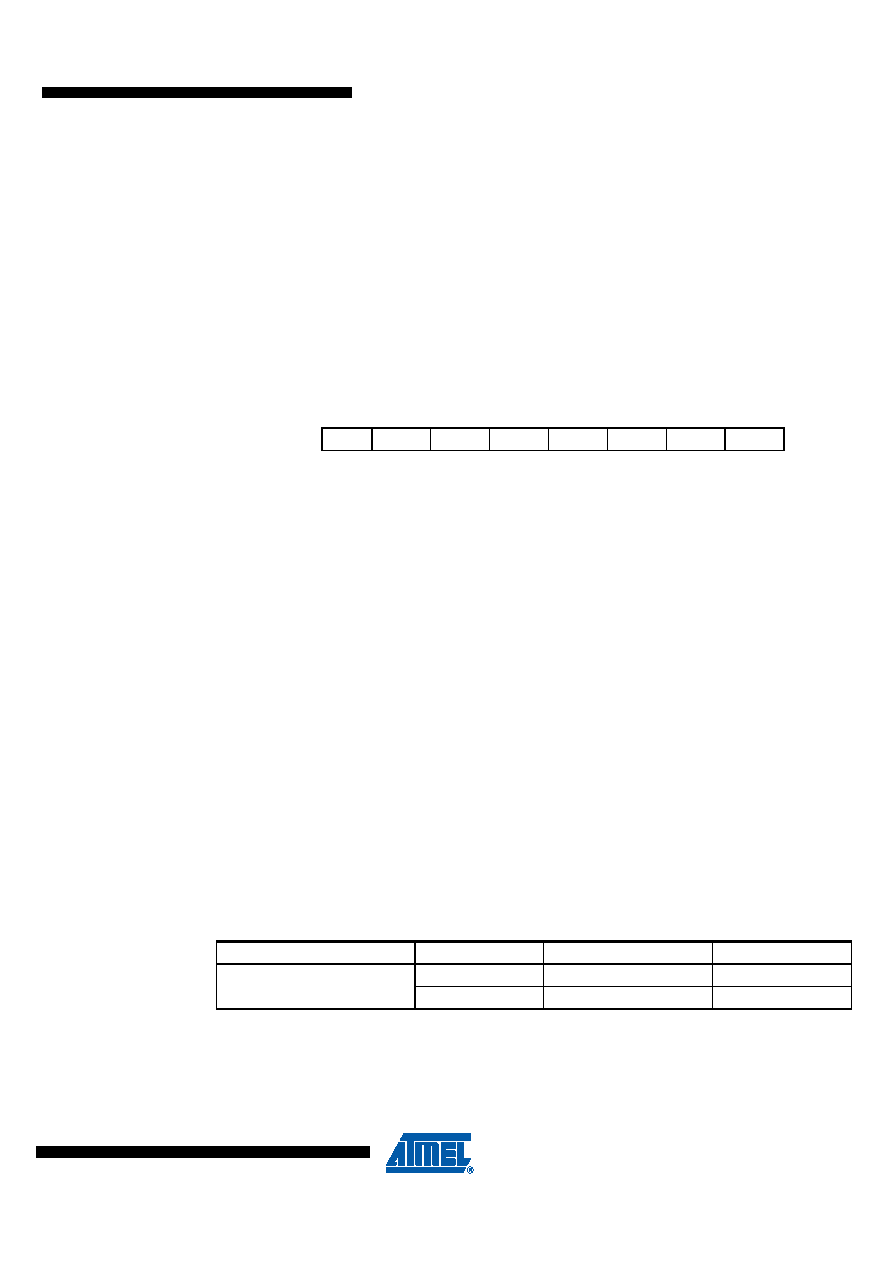
Slow Frequency RC – Oscillator Calibration Register – SRCCAL
Bits 7..0 - SCAL7..0: Slow frequency RC-oscillator CALibration Value
The Oscillator Calibration Register is used to trim the Calibrated Internal FRC Oscillator to
remove process variations from the Oscillator frequency. The factory-calibrated value is auto-
matically written to this register during chip reset, giving an oscillator frequency of 90kHz. The
application software can write this register to change the oscillator frequency. The oscillator can
be calibrated to any frequency in the range of 81kHz to 99kHz within 1% accuracy for a fixed
supply voltage and temperature. Calibration outside that range is not guaranteed.
The SCAL7 bit determines the range of operation for the oscillator. Setting this bit to 0 gives the
lowest frequency range, setting this bit to 1 gives the highest frequency range. The two fre-
quency ranges are overlapping, in other words a setting of SRCCAL = 0x7F gives a higher
frequency than SRCCAL = 0x80.
3.7.6
Clock Output Buffer
The device can output the system clock on the PC1/CLKO pin. To enable the output, the
CKOUT Fuse bit has to be programmed. This mode is suitable when the chip clock is used to
drive other circuits on the system. The clock also will be output during reset, and the normal
operation of I/O pin will be overridden when the fuse is programmed. Any clock source, including
the internal RC Oscillators, can be selected when the clock is output on CLKO. If the System
Clock Prescaler is used, it is the divided system clock that is output.
Bit
7
6543
210
SCAL7 SCAL6
SCAL5
SCAL4
SCAL3
SCAL2
SCAL1
SCAL0
SRCCAL
Read/Write
R/W
Initial Value
0
0000
000
Table 3-8.
Device Clock Output Select Description
(1)
Device Clock Output
CKOUT Fuse
Clock Name
Description
PC1(CLKO)
1
CLK
disabled
0
CLK
enabled
Note:
1. For all fues
“1” means unprogrammed while “0” means programmed
相關(guān)PDF資料 |
PDF描述 |
|---|---|
| A42MX16-3PL100 | 40MX and 42MX FPGA Families |
| A42MX16-3PL100A | 40MX and 42MX FPGA Families |
| A42MX16-3PQ100A | 40MX and 42MX FPGA Families |
| A42MX16-3VQ100 | 40MX and 42MX FPGA Families |
| A42MX16-3VQ100A | 40MX and 42MX FPGA Families |
相關(guān)代理商/技術(shù)參數(shù) |
參數(shù)描述 |
|---|---|
| A42MX16-3BG100A | 制造商:未知廠家 制造商全稱:未知廠家 功能描述:40MX and 42MX FPGA Families |
| A42MX16-3BG100B | 制造商:未知廠家 制造商全稱:未知廠家 功能描述:40MX and 42MX FPGA Families |
| A42MX16-3BG100ES | 制造商:未知廠家 制造商全稱:未知廠家 功能描述:40MX and 42MX FPGA Families |
| A42MX16-3BG100I | 制造商:未知廠家 制造商全稱:未知廠家 功能描述:40MX and 42MX FPGA Families |
| A42MX16-3BG100M | 制造商:未知廠家 制造商全稱:未知廠家 功能描述:40MX and 42MX FPGA Families |
發(fā)布緊急采購,3分鐘左右您將得到回復(fù)。