- 您現(xiàn)在的位置:買賣IC網(wǎng) > PDF目錄298744 > A42MX16-3BG100 (Electronic Theatre Controls, Inc.) 40MX and 42MX FPGA Families PDF資料下載
參數(shù)資料
| 型號: | A42MX16-3BG100 |
| 廠商: | Electronic Theatre Controls, Inc. |
| 英文描述: | 40MX and 42MX FPGA Families |
| 中文描述: | 40MX和42MX FPGA系列 |
| 文件頁數(shù): | 56/120頁 |
| 文件大小: | 854K |
| 代理商: | A42MX16-3BG100 |
第1頁第2頁第3頁第4頁第5頁第6頁第7頁第8頁第9頁第10頁第11頁第12頁第13頁第14頁第15頁第16頁第17頁第18頁第19頁第20頁第21頁第22頁第23頁第24頁第25頁第26頁第27頁第28頁第29頁第30頁第31頁第32頁第33頁第34頁第35頁第36頁第37頁第38頁第39頁第40頁第41頁第42頁第43頁第44頁第45頁第46頁第47頁第48頁第49頁第50頁第51頁第52頁第53頁第54頁第55頁當(dāng)前第56頁第57頁第58頁第59頁第60頁第61頁第62頁第63頁第64頁第65頁第66頁第67頁第68頁第69頁第70頁第71頁第72頁第73頁第74頁第75頁第76頁第77頁第78頁第79頁第80頁第81頁第82頁第83頁第84頁第85頁第86頁第87頁第88頁第89頁第90頁第91頁第92頁第93頁第94頁第95頁第96頁第97頁第98頁第99頁第100頁第101頁第102頁第103頁第104頁第105頁第106頁第107頁第108頁第109頁第110頁第111頁第112頁第113頁第114頁第115頁第116頁第117頁第118頁第119頁第120頁

40
4958B–AUTO–11/10
Atmel ATA6285/ATA6286 [Preliminary]
3.8.3
Sensor Noise Reduction Mode
When the SM2 ... 0 bits are written to “001”, the SLEEP instruction makes the MCU enter Sen-
sor Noise Reduction mode. This sleep mode basically halts CLK
CPU, CLKFLASH and CLKI/O while
allowing the other clocks to run. The FRC-oscillator is running and supply the timers with the
CLK
CLT.
If Timer2/3 are enabled, they will keep running during sleep. The device can wake up from either
Timer Overflow, Capture event or Output Compare event from Timer2/3 if the corresponding
Timer2/3 interrupt enable bits are set in T3IMR or T2IMR register, and the Global Interrupt
Enable bit in SREG register is set.
3.8.4
Power-down Mode
When the SM2..0 bits are written to “010”, the SLEEP instruction makes the MCU enter
Power-down mode. In this mode, the FRC-oscillator, an external input clock at ECIN0/ECIN1,
Voltage monitor and the Brown-out detection are stopped (when the BODPD bit is cleared),
while the external interrupts, and the Watchdog continue operating (if enabled). Only an External
Reset, a Watchdog Reset, LF-Receiver start condition interrupt, an external level interrupt on
INT0 or INT1, or a pin change interrupt can wake up the MCU. This sleep mode basically halts
all generated clocks except SCL if enabled, allowing operation of asynchronous modules only.
Note that if a level triggered interrupt is used for wake-up from Power-down mode, the changed
level must be held for some time to wake up the MCU. Refer to Section 3.11 “External Interrupts”
on page 49 for details.
When waking up from Power-down mode, there is a delay from the wake-up condition occurs
until the wake-up becomes effective. This allows the clock to restart and become stable after
having been stopped. The wake-up period is defined by the same SUT1..0 fusebits that define
the Reset Time-out period, as described in Section 3.7.3 “Clock Sources” on page 33.
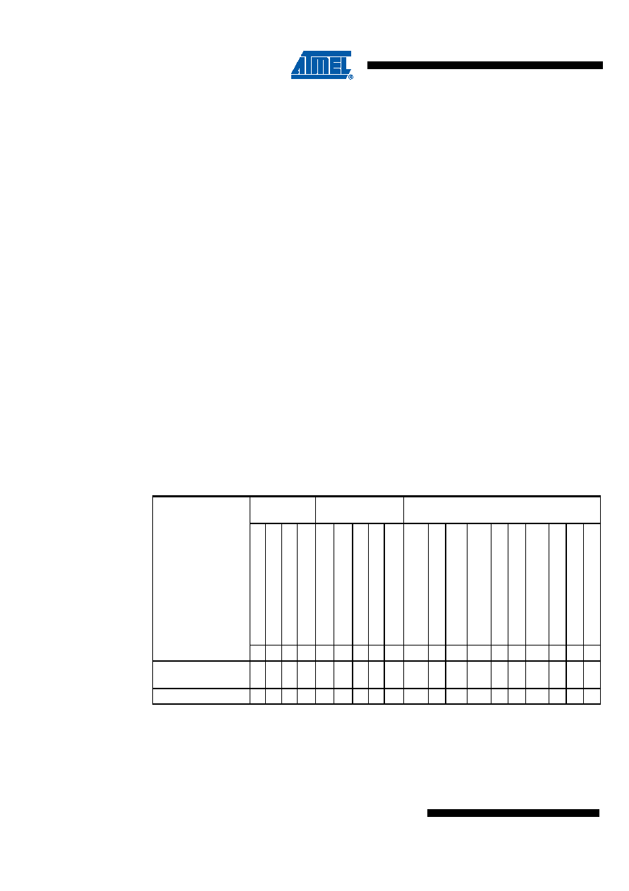
Table 3-12.
Active Clock Domains and Wake-up Sources in the Different Sleep Modes
Sleep Mode
Active Clock
Domains
Oscillators and
External Clocks
Wake-up Sources
clk
CP
U
clk
FLASH
clk
I/o
clk
CL
T
Exter
n
a
lCloc
k
FRC
SCH
SCL
IN
T0,
INT1
and
Pi
n
C
hang
e
L
F
-r
ec
ei
v
e
r
V
o
ltage
Mon
itor
Th
er
ma
lSh
utdo
wn
Sensor
Inte
rf
ace
WDT
BO
T
Time
r0
Time
r1
Time
r2
/3
IDLE
X
XX
X
XXX
Sensor Noise
Reduction
X
X(1)
X
XXX
Power-down
X
X(1)
XX(2) X(2)
XX
X(2)
XXX
Notes:
1. For INT1 and INT0, only level interrupt.
2. Only, when the BODPD is set bit in the VMCSR register.
相關(guān)PDF資料 |
PDF描述 |
|---|---|
| A42MX16-3PL100 | 40MX and 42MX FPGA Families |
| A42MX16-3PL100A | 40MX and 42MX FPGA Families |
| A42MX16-3PQ100A | 40MX and 42MX FPGA Families |
| A42MX16-3VQ100 | 40MX and 42MX FPGA Families |
| A42MX16-3VQ100A | 40MX and 42MX FPGA Families |
相關(guān)代理商/技術(shù)參數(shù) |
參數(shù)描述 |
|---|---|
| A42MX16-3BG100A | 制造商:未知廠家 制造商全稱:未知廠家 功能描述:40MX and 42MX FPGA Families |
| A42MX16-3BG100B | 制造商:未知廠家 制造商全稱:未知廠家 功能描述:40MX and 42MX FPGA Families |
| A42MX16-3BG100ES | 制造商:未知廠家 制造商全稱:未知廠家 功能描述:40MX and 42MX FPGA Families |
| A42MX16-3BG100I | 制造商:未知廠家 制造商全稱:未知廠家 功能描述:40MX and 42MX FPGA Families |
| A42MX16-3BG100M | 制造商:未知廠家 制造商全稱:未知廠家 功能描述:40MX and 42MX FPGA Families |
發(fā)布緊急采購,3分鐘左右您將得到回復(fù)。