- 您現(xiàn)在的位置:買賣IC網(wǎng) > PDF目錄376727 > DK1241A (Electronic Theatre Controls, Inc.) Advanced Microstepping Motion Control Chipset PDF資料下載
參數(shù)資料
| 型號(hào): | DK1241A |
| 廠商: | Electronic Theatre Controls, Inc. |
| 英文描述: | Advanced Microstepping Motion Control Chipset |
| 中文描述: | 高級(jí)微步運(yùn)動(dòng)控制芯片組 |
| 文件頁(yè)數(shù): | 18/60頁(yè) |
| 文件大?。?/td> | 422K |
| 代理商: | DK1241A |
第1頁(yè)第2頁(yè)第3頁(yè)第4頁(yè)第5頁(yè)第6頁(yè)第7頁(yè)第8頁(yè)第9頁(yè)第10頁(yè)第11頁(yè)第12頁(yè)第13頁(yè)第14頁(yè)第15頁(yè)第16頁(yè)第17頁(yè)當(dāng)前第18頁(yè)第19頁(yè)第20頁(yè)第21頁(yè)第22頁(yè)第23頁(yè)第24頁(yè)第25頁(yè)第26頁(yè)第27頁(yè)第28頁(yè)第29頁(yè)第30頁(yè)第31頁(yè)第32頁(yè)第33頁(yè)第34頁(yè)第35頁(yè)第36頁(yè)第37頁(yè)第38頁(yè)第39頁(yè)第40頁(yè)第41頁(yè)第42頁(yè)第43頁(yè)第44頁(yè)第45頁(yè)第46頁(yè)第47頁(yè)第48頁(yè)第49頁(yè)第50頁(yè)第51頁(yè)第52頁(yè)第53頁(yè)第54頁(yè)第55頁(yè)第56頁(yè)第57頁(yè)第58頁(yè)第59頁(yè)第60頁(yè)

18
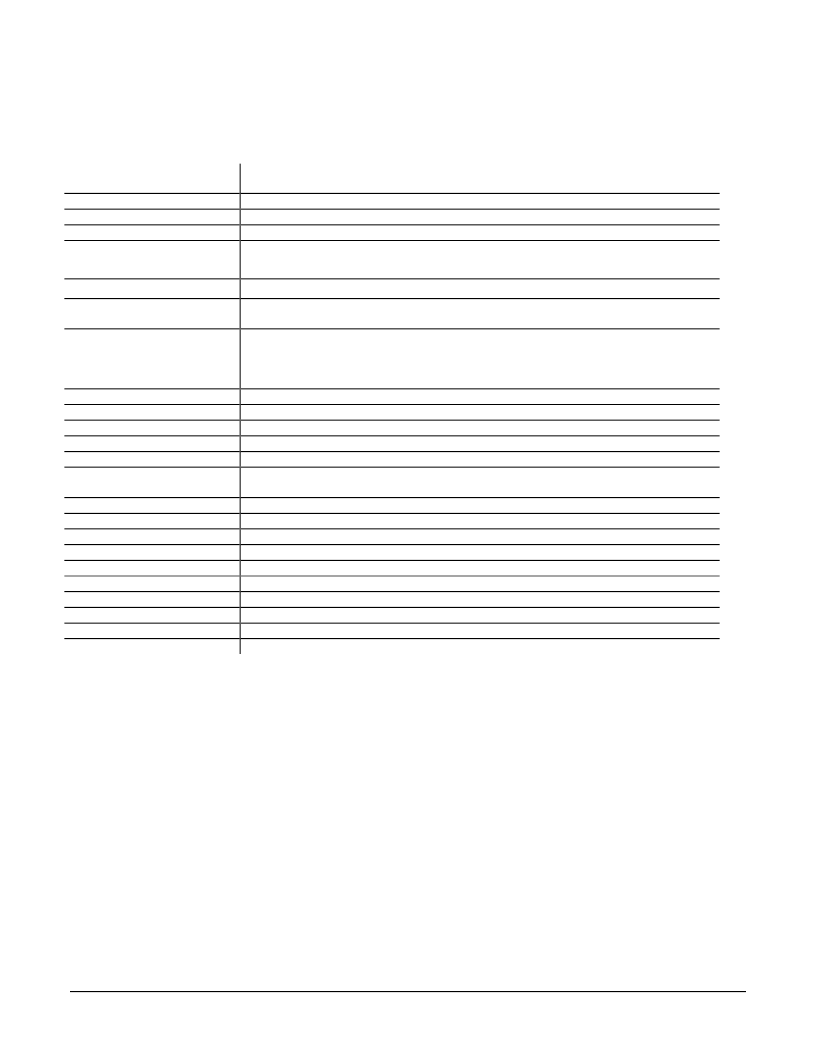
MC1241-Series Chipset Operational Parameters
Available configurations:
2 axes with internal mcrostepping generation (MC1241A)
1 axes with internal mcrostepping generation (MC1141A)
Open loop (motor is controlled directly by trajectory generator)
-1,073,741,824 to 1,073,741,823 usteps
-16,384 to 16,383 usteps/cycle with a resolution of 1/65,536 usteps/cycle
S-curve profile: - 1/2 to + 1/2 usteps/cycle2 with a resolution of 1/65,536 usteps/cycle2.
All others: -16,384 to 16,383 usteps/cycle2 with a resolution of 1/65,536 usteps/cycle2
-1/2 to +1/2 usteps/cycle3, with a resolution of 1/4,294,967,296 usteps/cycle3
-32,768 to +32,767 steps/cycle with a resolution of 1/65,536 steps/cycle
(used with trapezoidal and velocity profile modes only)
S-curve (host commands final position, max velocity, max acceleration, and jerk)
Trapezoidal (host commands final position, max velocity, starting velocity, and acceleration)
Velocity contouring (host commands max velocity, starting velocity, acceleration)
Electronic Gear (Encoder position is used as position command for corresponding axis).
32768:1 to 1:32768 (negative and positive direction)
A, B, Index
Sinusoidal
64
15 kHz
90 degrees (used with 2-phase stepper motors)
120 degrees (used with 3-phase stepper motors or AC Induction motors)
2 (all motor types)
97.6 kHz
8 bits
1.75 Mcounts/sec
540 uSec*
2 (one for each direction of travel)
Home switch input (one per axis)
2 (Index, Home signals)
160 nSec
80
Operating Modes:
Position Range:
Velocity Range:
Acceleration Range:
Jerk Range:
Start velocity range
Trajectory Profile Generator Modes:
Electronic Gear Ratio Range:
Encoder Input Signals:
Mcrostepping Waveform
#Steps Per Full Step:
Mcrostep Lookup Rate:
Phasing:
#of Output Phases:
PWMFrequency:
PWMresolution:
Max Incremental. Encoder Rate:
Profile Cycle Rate :
#of Limt Switch Inputs Per Axis
Mscellaneous control lines:
#of Position Capture Sources:
Capture Trigger Latency:
#of Host Commands:
*Exact cycle time is 542.72 uSec, 540 is an approximation
Trajectory Profile Generation
The trajectory profile generator performs calculations to determne the
target position, velocity and acceleration on a continuous basis. These
calculations are performed taking into account the current profile mode,
as well as the current profile parameters set by the host. Four trajectory
profile modes are supported:
- S-curve point to point
- Trapezoidal point to point
- Velocity contouring
- Electronic Gear
The commands to select these profile modes are
SET_PRFL_S_CRV (to select the s-curve mode), SET_PRFL_TRAP
(to select the trapezoidal mode) SET_PRFL_VEL (to select the
velocity contouring mode) and SET_PRFL_GEAR (to select the
electronic gear mod).
Throughout this manual various command mnemonics will be
shown to clarify chipset usage or provide specific examples. See
the Host Communications section for a description of host
command nomenclature.
相關(guān)PDF資料 |
PDF描述 |
|---|---|
| DK2100 | Navigator Motion Processor |
| DK3300 | Turbo uPSD DK3300 User Manual(Turbo系列 uPSD DK3300 用戶手冊(cè)) |
| DK60 | DIODY PROSTOWNICZE |
| DK61 | DIODY PROSTOWNICZE |
| DK62 | DIODY PROSTOWNICZE |
相關(guān)代理商/技術(shù)參數(shù) |
參數(shù)描述 |
|---|---|
| DK125950 | 制造商:TE Connectivity 功能描述: |
| DK-125M-1 | 制造商:Luminus Devices 功能描述:EVAL BOARD & HEAT SINK FOR PT85/CBT85. MAX16818, 25A, 1 CH - Bulk |
| DK12GY | 功能描述:電氣外殼 RoHS:否 制造商:Bud Industries 產(chǎn)品:Wall Mount Enclosures 類型:Single Door NEMA 額定值:3R 外部深度:254 mm 外部高度:305 mm 外部寬度:305 mm 面板寬度:261 mm 面板高度:261 mm 材料:Steel 顏色:Gray 通風(fēng):Not Available |
| DK12LG | 功能描述:電氣外殼 RoHS:否 制造商:Bud Industries 產(chǎn)品:Wall Mount Enclosures 類型:Single Door NEMA 額定值:3R 外部深度:254 mm 外部高度:305 mm 外部寬度:305 mm 面板寬度:261 mm 面板高度:261 mm 材料:Steel 顏色:Gray 通風(fēng):Not Available |
| DK12S16 | 功能描述:電氣外殼 RoHS:否 制造商:Bud Industries 產(chǎn)品:Wall Mount Enclosures 類型:Single Door NEMA 額定值:3R 外部深度:254 mm 外部高度:305 mm 外部寬度:305 mm 面板寬度:261 mm 面板高度:261 mm 材料:Steel 顏色:Gray 通風(fēng):Not Available |
發(fā)布緊急采購(gòu),3分鐘左右您將得到回復(fù)。