- 您現(xiàn)在的位置:買賣IC網(wǎng) > PDF目錄377484 > IDT77V1254L25L25PGI (Integrated Device Technology, Inc.) Quad Port PHY (Physical Layer) for 25.6 and 51.2 ATM Networks PDF資料下載
參數(shù)資料
| 型號: | IDT77V1254L25L25PGI |
| 廠商: | Integrated Device Technology, Inc. |
| 英文描述: | Quad Port PHY (Physical Layer) for 25.6 and 51.2 ATM Networks |
| 中文描述: | 四端口PHY(實體層)為25.6和51.2 ATM網(wǎng)絡(luò) |
| 文件頁數(shù): | 16/47頁 |
| 文件大小: | 840K |
| 代理商: | IDT77V1254L25L25PGI |
第1頁第2頁第3頁第4頁第5頁第6頁第7頁第8頁第9頁第10頁第11頁第12頁第13頁第14頁第15頁當(dāng)前第16頁第17頁第18頁第19頁第20頁第21頁第22頁第23頁第24頁第25頁第26頁第27頁第28頁第29頁第30頁第31頁第32頁第33頁第34頁第35頁第36頁第37頁第38頁第39頁第40頁第41頁第42頁第43頁第44頁第45頁第46頁第47頁
16 of 47
September 21, 2001
IDT77V1254L25
Instead, key handshaking signals are duplicated so that each
channel has its own signals. In both versions of UTOPIA, all channels
share a single transmit data bus and a single receive data bus for data
transfer.
DPI is a low-pin count Physical Layer to ATM Layer interface. The
low-pin count characteristic allows the 77V1254L25 to incorporate four
separate DPI 4-bit ports, one for each of the four serial ports. As with the
UTOPIA interfaces, the transmit and receive directions have their own
data paths and handshaking.
UTOPIA Level 2 Interface option
The 16-bit Utopia Level 2 interface operates as defined in ATM
Forum document af-phy-0039. This PHY-ATM interface is selected by
setting the MODE[1:0] pins both low.
This mode is configured as a single 16-bit data bus in the transmit
(ATM-to-PHY) direction, and a single 16-bit data bus in the receive
(PHY-to-ATM) direction. In addition to the data bus, each direction also
includes a single optional parity bit, an address bus, and several hand-
shaking signals. The UTOPIA address of each channel is determined by
bits 4 to 0 in the Enhanced Control Registers. Please note that the
transmit bus and the receive bus operate completely independently. The
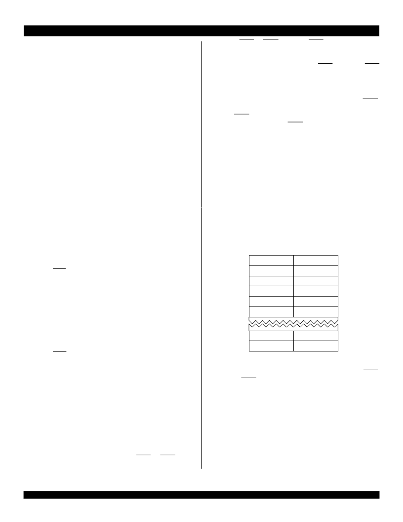
Utopia 2 signals are summarized below:
To determine if any of them has room to accept a cell for transmis-
sion (TXCLAV), or has a receive cell available to pass on to the ATM
device (RXCLAV). To poll, the ATM device drives an address (TXADDR
or RXADDR) then observes TXCLAV or RXCLAV on the next cycle of
TXCLK or RXCLK. A port must tri-state TXCLAV and RXCLAV except
when it is addressed.
If TXCLAV or RXCLAV is asserted, the ATM device may select that
port, then transfer a cell to or from it. Selection of a port is performed by
driving the address of the desired port while TXEN or RXEN is high,
TXDATA[15:0]
ATM to PHY
TXPARITY
ATM to PHY
TXSOC
ATM to PHY
TXADDR[4:0]
ATM to PHY
TXEN
ATM to PHY
TXCLAV
PHY to ATM
TXCLK
ATM to PHY
RXDATA[15:0]
RXPARITY
RXSOC
RXADDR[4:0]
PHY to ATM
PHY to ATM
PHY to ATM
ATM to PHY
ATM to PHY
PHY to ATM
RXEN
RXCLAV
RXCLK
ATM to PHY
then driving TXEN or RXEN low. When TXEN is driven low, TXSOC
(start of cell) is driven high to indicate that the first 16 bits of the cell are
being driven on TXDATA. The ATM device may chose to temporarily
suspend transfer of the cell by deasserting TXEN. Otherwise, TXEN
remains asserted as the next 16 bits are driven onto TXDATA with each
cycle of TXCLK.
In the receive direction, the ATM device selects a port if it wished to
receive the cell that the port is holding. It does this by asserting RXEN.
The PHY then transfers the data 16 bits each clock cycle, as deter-
mined by RXEN. As in the transmit direction, the ATM device may
suspend transfer by deasserting RXEN at any time. Note that the PHY
asserts RXSOC coincident with the first 16 bits of each cell.
TXPARITY and RXPARITY are parity bits for the corresponding 16-
bit data fields. Odd parity is used.
Figure 9 through Figure 14 may be referenced for Utopia 2 bus
examples.
Because this interface transfers an even number of bytes, rather
than the ATM standard of 53 bytes, a filler byte is inserted between the
5-byte header and the 48-byte payload. This is shown in Figure 8.
UTOPIA Level 1 multi-phy interface Option
The UTOPIA Level 1 MULTI-PHY interface is based on ATM Forum
document af-phy-0017. Utopia Level 1 is essentially the same as Utopia
Level 2, but without the addressing, polling and selection features.
Figure 6 Utopia Level 2 Data Format and Sequence
Instead of addressing, this mode utilizes separate TXCLAV, TXEN,
RXCLAV and RXEN signals for each channel of the 77V1254L25. There
are just one each of the TXSOC and RXSOC signals, which are shared
across all four channels.
In addition to Utopia Level 2's cell mode transfer protocol, Utopia
Level 1 also offers the option of a byte mode protocol. Bit 1 of the
Master Control Registers is used to program whether the UTOPIA Level
1 bus is in cell mode or byte mode. In byte mode, the PHY is allowed to
control data transfer on a byte-by-byte basis via the TXCLAV and
RXCLAV signals. In cell mode, TXCLAV and RXCLAV are ignored once
;00 0
;00 0
;00 0
' 0
' 0
' 0
' 0 "
;00 0
;00 0 "
8:<< 0
' 0
' 0 "
' 0 #
' 0 "#
' 0 "$
'0 "%
25
25
-58
8
相關(guān)PDF資料 |
PDF描述 |
|---|---|
| IDT77V1254L25 | Quad Port PHY (Physical Layer) for 25.6 and 51.2 ATM Networks |
| IDT77V1254L25L25PG | Quad Port PHY (Physical Layer) for 25.6 and 51.2 ATM Networks |
| IDT79RC64V475250DZ | RISControllerTM Embedded 64-bit Microprocessor, based on RISCore4000 |
| IDT79RC64V475250DZI | RISControllerTM Embedded 64-bit Microprocessor, based on RISCore4000 |
| IDT79RC64V474180DZI | RISControllerTM Embedded 64-bit Microprocessor, based on RISCore4000 |
相關(guān)代理商/技術(shù)參數(shù) |
參數(shù)描述 |
|---|---|
| IDT77V252L155PG | 制造商:Integrated Device Technology Inc 功能描述:ATM/SONET SEGMENTATION AND REASSEMBLY CIRCUIT, 208 Pin, Plastic, QFP |
| IDT77V400S156BC | 功能描述:IC SW MEMORY 8X8 1.2BGPS 256-BGA RoHS:否 類別:集成電路 (IC) >> 專用 IC 系列:SwitchStar™ 產(chǎn)品培訓(xùn)模塊:Lead (SnPb) Finish for COTS Obsolescence Mitigation Program 標(biāo)準(zhǔn)包裝:1 系列:- 類型:調(diào)幀器 應(yīng)用:數(shù)據(jù)傳輸 安裝類型:表面貼裝 封裝/外殼:400-BBGA 供應(yīng)商設(shè)備封裝:400-PBGA(27x27) 包裝:散裝 |
| IDT77V400S156BCG | 功能描述:IC SW MEMORY 8X8 1.2BGPS 256-BGA RoHS:是 類別:集成電路 (IC) >> 專用 IC 系列:SwitchStar™ 產(chǎn)品培訓(xùn)模塊:Lead (SnPb) Finish for COTS Obsolescence Mitigation Program 標(biāo)準(zhǔn)包裝:1 系列:- 類型:調(diào)幀器 應(yīng)用:數(shù)據(jù)傳輸 安裝類型:表面貼裝 封裝/外殼:400-BBGA 供應(yīng)商設(shè)備封裝:400-PBGA(27x27) 包裝:散裝 |
| IDT77V400S156DS | 功能描述:IC SW MEMORY 8X8 1.2BGPS 208PQFP RoHS:否 類別:集成電路 (IC) >> 專用 IC 系列:SwitchStar™ 產(chǎn)品培訓(xùn)模塊:Lead (SnPb) Finish for COTS Obsolescence Mitigation Program 標(biāo)準(zhǔn)包裝:1 系列:- 類型:調(diào)幀器 應(yīng)用:數(shù)據(jù)傳輸 安裝類型:表面貼裝 封裝/外殼:400-BBGA 供應(yīng)商設(shè)備封裝:400-PBGA(27x27) 包裝:散裝 |
| IDT77V500S25BC | 功能描述:IC SW MEMORY 8X8 1.2BGPS 144-BGA RoHS:否 類別:集成電路 (IC) >> 專用 IC 系列:SwitchStar™ 產(chǎn)品培訓(xùn)模塊:Lead (SnPb) Finish for COTS Obsolescence Mitigation Program 標(biāo)準(zhǔn)包裝:1 系列:- 類型:調(diào)幀器 應(yīng)用:數(shù)據(jù)傳輸 安裝類型:表面貼裝 封裝/外殼:400-BBGA 供應(yīng)商設(shè)備封裝:400-PBGA(27x27) 包裝:散裝 |
發(fā)布緊急采購,3分鐘左右您將得到回復(fù)。