- 您現(xiàn)在的位置:買賣IC網(wǎng) > PDF目錄371179 > T7121-PL2 T7121 HDLC Interface for ISDN PDF資料下載
參數(shù)資料
| 型號: | T7121-PL2 |
| 英文描述: | T7121 HDLC Interface for ISDN |
| 中文描述: | T7121的HDLC接口用于ISDN |
| 文件頁數(shù): | 14/68頁 |
| 文件大小: | 685K |
| 代理商: | T7121-PL2 |
第1頁第2頁第3頁第4頁第5頁第6頁第7頁第8頁第9頁第10頁第11頁第12頁第13頁當(dāng)前第14頁第15頁第16頁第17頁第18頁第19頁第20頁第21頁第22頁第23頁第24頁第25頁第26頁第27頁第28頁第29頁第30頁第31頁第32頁第33頁第34頁第35頁第36頁第37頁第38頁第39頁第40頁第41頁第42頁第43頁第44頁第45頁第46頁第47頁第48頁第49頁第50頁第51頁第52頁第53頁第54頁第55頁第56頁第57頁第58頁第59頁第60頁第61頁第62頁第63頁第64頁第65頁第66頁第67頁第68頁

14
Lucent Technologies Inc.
Data Sheet
April 1997
T7121 HDLC Interface for ISDN (HIFI-64)
Functional Description
(continued)
Similarly for the receiver, the receive bit offset RBOF (R9—B[3—1]) and the receive time-slot offset RTSOF
(R11—B[5—0]) determine where the first bit of the first receive time slot is found. The time slot used is selected by
the value of the receiver time-slot RSLT (R8—B[5—0]). The first bit is received
RBOF + (8 x RTSOF) + (8 x RSLT) = M
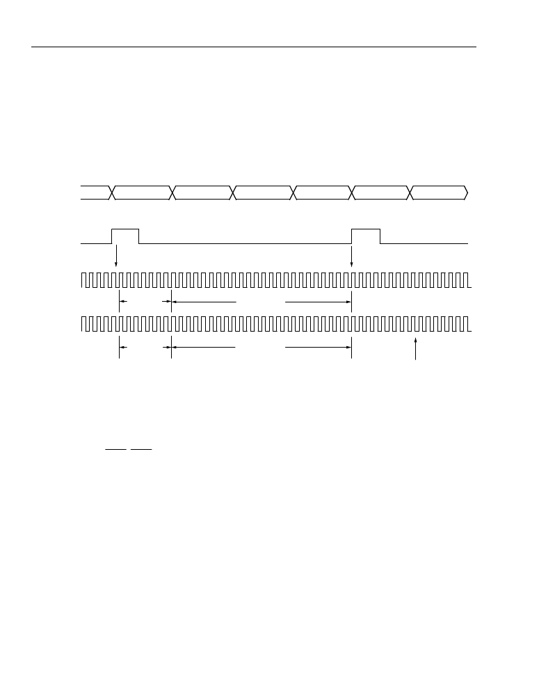
bit times after the beginning of the TDM frame. Figure 5 illustrates using the offsets to configure a system consist-
ing of four time slots, where the initial time slot aligns with the FS. For this system, FE = 0, CLKXI = 1, CLKRI = 0,
TSLT = 000000, and RSLT = 000001.
5-5031
Figure 5. Maximum Bit and Time-Slot Offsets for a Four Time-Slot System
Transmission During Unassigned Time Slots
During time slots when the HIFI-64 is not transmitting, the transmit data output 3-states (an external pull-up resistor
is recommended). This also occurs during masked bit times during a time slot (see the Bit Masking section). If pin
17 is configured to
TSCA
,
TSCA
is high during all time slots other than the assigned time slot and during masked bit
times in the assigned time slot.
Bit Order During Transmission
Data transmission is normally least significant bit (LSB) first per HDLC protocol specifications. In transparent mode,
data is also generated least significant bit first. However, when in the TDM highway mode (HWYEN R0—B7 = 1),
the order of transmission and the expected order for receiving can be reversed by programming the TLBIT and
RLBIT (R10—B6) and (R11—B6), respectively. These bits can be programmed independently of one another. In
other words, the HIFI-64 can be receiving LSB first but transmitting most significant bit (MSB) first, or vice versa.
The effect of TLBIT cleared to 0 is to reverse end-for-end the transmitter-generated data before transmission in the
time slot. All data is reversed, including flags, aborts, CRC, and user data. The effect of RLBIT cleared to 0 is to
reverse end-for-end the time-slot data before passing it to the receiver. RLBIT and TLBIT have no effect on the data
unless HWYEN (R0—B7) = 1.
Figures 6 and 7 show how the transmission and reception of data is affected by adjusting TLBIT and RLBIT. The
convention used represents user data in the FIFO with lower-case letters and HDLC data as upper-case letters.
This convention is meant to indicate only that data in the FIFO and data transmitted or received during the time
slot(s) may not be identical bit-for-bit (i.e., zero-bit insertion and deletion—see the HDLC section of this document).
TS 0
TS 1
TS 2
TS 3
TS 0
TS 1
TDM DATA
FS
CLKX
CLKR
FIRST BIT
RECEIVED
TTSOF = 000011
RTSOF = 000011
TBOF = 111
RBOF = 111
FS LATCHED ON THIS EDGE
FIRST BIT TRANSMITTED
相關(guān)PDF資料 |
PDF描述 |
|---|---|
| T7121 | HDLC Interface for ISDN (HIFI-64)(應(yīng)用于ISDN的HDLC(高階數(shù)據(jù)鏈路)接口) |
| T7502 | T7502 Dual PCM Codec with Filters |
| T7503 | T7503 Dual PCM Codec with Filters |
| T7504 | T7504 and T75504 Quad PCM Codecs with Filters |
| T7507 | T7507 Quad PCM Codec with Filters, Termination Impedance, and Hybrid Balance |
相關(guān)代理商/技術(shù)參數(shù) |
參數(shù)描述 |
|---|---|
| T7122 | 制造商:未知廠家 制造商全稱:未知廠家 功能描述:TRIANGULAR TYPE |
| T7-122A1 | 功能描述:撥動(dòng)開關(guān) ON NONE OFF 1 Pole Low-Level Bat Handle RoHS:否 制造商:OTTO 觸點(diǎn)形式: 開關(guān)功能: 電流額定值: 電壓額定值 AC: 電壓額定值 DC: 功率額定值: 端接類型: 安裝風(fēng)格: 端子密封: 觸點(diǎn)電鍍: 照明: |
| T7-122B1 | 功能描述:撥動(dòng)開關(guān) ON NONE ON 1 Pole Low-Level Bat Handle RoHS:否 制造商:OTTO 觸點(diǎn)形式: 開關(guān)功能: 電流額定值: 電壓額定值 AC: 電壓額定值 DC: 功率額定值: 端接類型: 安裝風(fēng)格: 端子密封: 觸點(diǎn)電鍍: 照明: |
| T7-122D1 | 制造商:OTTO 功能描述:Toggle Switches (ON) NONE ON 1 Pole Low-Level Bat Handle 制造商:OTTO Engineering Inc 功能描述:Switch Toggle (ON) None ON SPDT Bat Toggle Screw 16A 115VAC 28VDC Panel Mount with Threads |
| T7-122E1 | 制造商:OTTO 功能描述:Toggle Switches (ON) OFF (ON) 1 Pole Low-Level Bat Handle 制造商:OTTO Engineering Inc 功能描述:Switch Toggle (ON) OFF (ON) SPDT Bat Toggle Screw 16A 115VAC 28VDC Panel Mount with Threads |
發(fā)布緊急采購,3分鐘左右您將得到回復(fù)。