- 您現(xiàn)在的位置:買賣IC網(wǎng) > PDF目錄373891 > AD6636CBCZ1 (Analog Devices, Inc.) 150 MSPS Wideband Digital Down-Converter (DDC) PDF資料下載
參數(shù)資料
| 型號: | AD6636CBCZ1 |
| 廠商: | Analog Devices, Inc. |
| 元件分類: | 數(shù)字上/下變頻 |
| 英文描述: | 150 MSPS Wideband Digital Down-Converter (DDC) |
| 中文描述: | 150MSPS的寬帶數(shù)字下變頻器(DDC) |
| 文件頁數(shù): | 11/72頁 |
| 文件大?。?/td> | 1629K |
| 代理商: | AD6636CBCZ1 |
第1頁第2頁第3頁第4頁第5頁第6頁第7頁第8頁第9頁第10頁當(dāng)前第11頁第12頁第13頁第14頁第15頁第16頁第17頁第18頁第19頁第20頁第21頁第22頁第23頁第24頁第25頁第26頁第27頁第28頁第29頁第30頁第31頁第32頁第33頁第34頁第35頁第36頁第37頁第38頁第39頁第40頁第41頁第42頁第43頁第44頁第45頁第46頁第47頁第48頁第49頁第50頁第51頁第52頁第53頁第54頁第55頁第56頁第57頁第58頁第59頁第60頁第61頁第62頁第63頁第64頁第65頁第66頁第67頁第68頁第69頁第70頁第71頁第72頁

AD6636
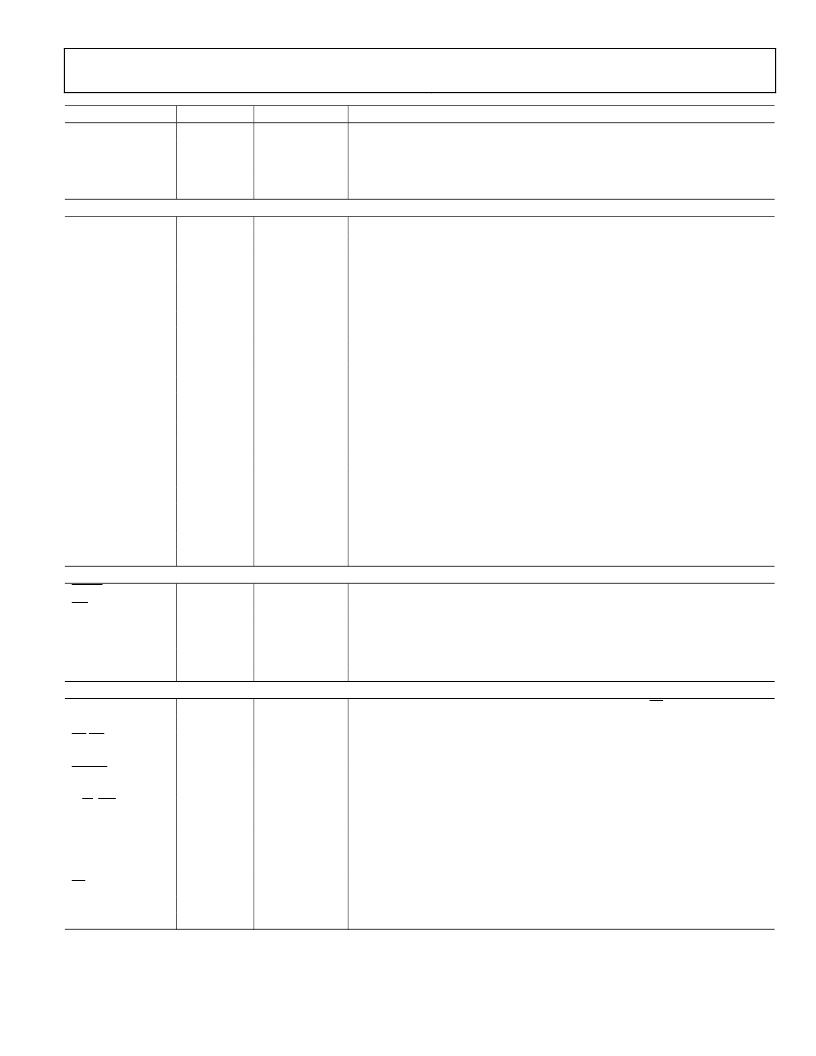
Name
CLKC, CLKD
INA[0:15], INB[0:15]
Rev. 0 | Page 11 of 72
Type
Input
LVDS Input
Pin No.
A6, A5
See Table 8
Function
LVDS Differential Clock for LVDS_C Input Port (LVDS_CLKC+, LVDS_CLKC).
In LVDS input mode, INA[0 :15] and INB[0 :15] form a differential pair
LVDS_A+[0:15] (positive node) and LVDS_A–[0:15] (negative node), respectively.
In LVDS input mode, INC[0 :15] and IND[0 :15] form a differential pair
LVDS_C+[0:15] (positive node) and LVDS_C–[0:15] (negative node), respectively.
INC[0:15], IND[0:15]
LVDS Input
See Table 8
OUTPUT PORTS
PCLK
PA[0:15]
PACH[0:2]
PAIQ
PAGAIN
Bidirectional
Output
Output
Output
Output
E16
See Table 8
G15, D16, H12
H13
G13
Parallel Output Port Clock. Master mode output, Slave mode input.
Parallel Output Port A Data Bus.
Channel Indicator Output Port A.
Parallel Port A I/Q Data Indicator. Logic 1 indicates I data on data bus.
Parallel Port A Gain Word Output Indicator. Logic 1 indicates gain word on
data bus.
Parallel Port A Acknowledge (Active High).
Parallel Port A Request (Active High).
Parallel Output Port B Data Bus.
Channel Indicator Output Port B.
Parallel Port B I/Q Data Indicator. Logic 1 indicates I data on data bus.
Parallel Port B Gain Word Output Indicator. Logic 1 indicates gain word on
data bus.
Parallel Port B Acknowledge (Active High).
Parallel Port B Request (Active High).
Parallel Output Port C Data Bus.
Channel Indicator Output Port C.
Parallel Port C I/Q Data Indicator. Logic 1 indicates I data on data bus.
Parallel Port C Gain Word Output Indicator. Logic 1 indicates gain word on
data bus.
Parallel Port C Acknowledge (Active High).
Parallel Port C Request (Active High).
PAACK
PAREQ
PB[0:15]
PBCH[0:2]
PBIQ
PBGAIN
Input
Output
Output
Output
Output
Output
H14
F15
See Table 8
C13, D11, B14
D12
A14
PBACK
PBREQ
PC[0:15]
PCCH[0:2]
PCIQ
PCGAIN
Input
Output
Output
Output
Output
Output
E12
E11
See Table 8
M15, L14, N15
P15
P16
PCACK
PCREQ
MISC PINS
RESET
IRP
SYNC[0:3]
Input
Output
L13
R16
Input
Output
Input
P3
T2
B12, A12, C10,
B11
E4
R4
Master Reset (Active Low).
Interrupt Pin.
Synchronization Inputs. SYNC pins are independent of channels or input ports and
independent of each other.
LVDS Resistor Set Pin (Analog Pin). See Design Notes.
PLL Loop Filter (Analog Pin). See Design Notes.
LVDS_RSET
EXT_FILTER
MICROPORT CONTROL
D[0:15]
A[0:7]
DS(RD)
Input
Input
Bidirectional
Input
Input
See Table 8
See Table 8
P4
Bidirectional Microport Data. This bus is three-stated when CS is high.
Microport Address Bus.
Active Low Data Strobe when MODE = 1.
Active Low Read Strobe when MODE = 0.
Active Low Data Acknowledge when MODE = 1.
Microport Status Pin when MODE = 0.
Read/Write Strobe when MODE = 1.
Active Low Write Strobe when MODE = 0.
Mode Select Pin.
When SMODE = 0: Logic 0 = Intel mode; Logic 1 = Motorola mode.
When SMODE = 1: Logic 0 = SPI mode; Logic 1 = SPORT mode.
Active Low Chip Select. Logic 1 three-states the microport data bus.
Microport CLK Input (Input Only).
Chip ID Input Pins.
DTACK (RDY)
1
Output
M6
R/W (WR)
Input
N4
MODE
Input
T3
CS
CPUCLK
CHIPID[0:3]
Input
Input
Input
N5
R1
T4, R5, N6, P6
相關(guān)PDF資料 |
PDF描述 |
|---|---|
| AD6636PCB | 150 MSPS Wideband Digital Down-Converter (DDC) |
| AD664(中文) | Monolithic 12-Bit Quad DAC(單片12位四D/A轉(zhuǎn)換器) |
| AD6640 | 12-Bit, 65 MSPS IF Sampling A/D Converter |
| AD6640AST | 12-Bit, 65 MSPS IF Sampling A/D Converter |
| AD6640PCB | 12-Bit, 65 MSPS IF Sampling A/D Converter |
相關(guān)代理商/技術(shù)參數(shù) |
參數(shù)描述 |
|---|---|
| AD6636PCB | 制造商:AD 制造商全稱:Analog Devices 功能描述:150 MSPS Wideband Digital Down-Converter (DDC) |
| AD6636XBCZ | 制造商:Analog Devices 功能描述: |
| AD664 | 制造商:AD 制造商全稱:Analog Devices 功能描述:Monolithic 12-Bit Quad DAC |
| AD6640 | 制造商:AD 制造商全稱:Analog Devices 功能描述:12-Bit, 65 MSPS IF Sampling A/D Converter |
| AD6640AST | 制造商:Analog Devices 功能描述:ADC Single Pipelined 65Msps 12-bit Parallel 44-Pin LQFP 制造商:Analog Devices 功能描述:ADC SGL PIPELINED 65MSPS 12-BIT PARALLEL 44LQFP - Trays 制造商:Rochester Electronics LLC 功能描述:12-BIT 65 MSPS MONOLITHIC A/D CONVERTER - Tape and Reel 制造商:Analog Devices 功能描述:Analog-Digital Converter IC Number of Bi |
發(fā)布緊急采購,3分鐘左右您將得到回復(fù)。