- 您現(xiàn)在的位置:買賣IC網(wǎng) > PDF目錄18714 > AD9852/PCBZ (Analog Devices Inc)BOARD EVAL FOR AD9852 PDF資料下載
參數(shù)資料
| 型號: | AD9852/PCBZ |
| 廠商: | Analog Devices Inc |
| 文件頁數(shù): | 10/52頁 |
| 文件大小: | 0K |
| 描述: | BOARD EVAL FOR AD9852 |
| 設(shè)計資源: | AD9852 Eval Brd BOM AD9852 Schematic |
| 標(biāo)準(zhǔn)包裝: | 1 |
| 系列: | AgileRF™ |
| 類型: | 合成器 |
| 適用于相關(guān)產(chǎn)品: | AD9852 |
| 相關(guān)產(chǎn)品: | AD9852ASVZ-ND - IC DDS SYNTHESIZER CMOS 80-TQFP AD9852ASTZ-ND - IC DDS SYNTHESIZER CMOS 80-LQFP |
第1頁第2頁第3頁第4頁第5頁第6頁第7頁第8頁第9頁當(dāng)前第10頁第11頁第12頁第13頁第14頁第15頁第16頁第17頁第18頁第19頁第20頁第21頁第22頁第23頁第24頁第25頁第26頁第27頁第28頁第29頁第30頁第31頁第32頁第33頁第34頁第35頁第36頁第37頁第38頁第39頁第40頁第41頁第42頁第43頁第44頁第45頁第46頁第47頁第48頁第49頁第50頁第51頁第52頁

AD9852
Rev. E | Page 18 of 52
MODES OF OPERATION
There are five programmable modes of operation of the AD9852.
Selecting a mode requires that three bits in the control register
(Parallel Address 1F hex) be programmed as shown in Table 6.
Table 6. Mode Selection Table
Mode 2
Mode 1
Mode 0
Result
0
Single tone
0
1
FSK
0
1
0
Ramped FSK
0
1
Chirp
1
0
BPSK
In each mode, engaging certain functions may be prohibited.
Table 7 lists some important functions and their availability for
each mode.
SINGLE TONE (MODE 000)
When the MASTER RESET pin is asserted, single-tone mode
becomes the default. The user can also access this mode by
programming it into the control register. The phase accumulator,
responsible for generating an output frequency, is presented with
a 48-bit value from the Frequency Tuning Word 1 registers with
default values of 0. Default values from the remaining applicable
registers further define the single-tone output signal qualities.
The default values after a master reset configures the device
with an output signal of 0 Hz and zero phase. Upon power-up
and reset, the output from both DACs is a dc value equal to the
midscale output current. This is the default mode amplitude setting
of 0. Refer to the On/Off Output Shaped Keying (OSK) section
for further explanation of the output amplitude control. It is
necessary to program all or some of the 28 program registers to
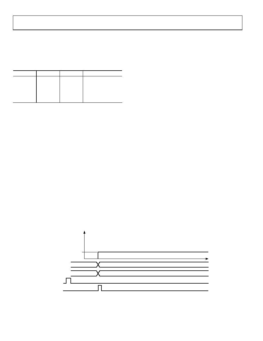
produce a user-defined output signal. Figure 32 shows the
transition from the default condition (0 Hz) to a user-defined
output frequency (F1).
As with all Analog Devices DDS devices, the value of the frequency
tuning word is determined using the following equation:
FTW = (Desired Output Frequency × 2N)/SYSCLK
where:
N is the phase accumulator resolution (48 bits in this instance).
Desired Output Frequency is expressed in hertz.
FTW (frequency tuning word) is a decimal number.
After a decimal number has been calculated, it must be rounded
to an integer and then converted to binary format—a series of
48 binary-weighted 1s and 0s. The fundamental sine wave DAC
output frequency range is from dc to one-half SYSCLK.
Changes in frequency are phase continuous; therefore, the first
sampled phase value of the new frequency is referenced from the
time of the last sampled phase value of the previous frequency.
The 14-bit phase register adjusts the cosine DAC’s output phase.
The single-tone mode allows the user to control the following
signal qualities:
Output frequency to 48-bit accuracy
Output amplitude to 12-bit accuracy
Fixed, user-defined amplitude control
Variable, programmable amplitude control
Automatic, programmable, single-pin-controlled
on/off output shaped keying
Output phase to 14-bit accuracy
Furthermore, all of these qualities can be changed or modulated
via the 8-bit parallel programming port at a 100 MHz parallel
byte rate or at a 10 MHz serial rate. Incorporating this attribute
permits FM, AM, PM, FSK, PSK, and ASK operation in the
single-tone mode.
000 (SINGLE TONE)
MODE
F1
TW1
000 (DEFAULT)
0
F1
0
FREQUENCY
MASTER RESET
I/O UD CLK
00634-032
Figure 32. Default State to User-Defined Output Transition
相關(guān)PDF資料 |
PDF描述 |
|---|---|
| X24-009-DK | KIT DEV 2.4GHZ 9600BPS W/RPSMA |
| 0622022510 | TOOL INSERTION 30POS 3ROWS |
| TC70V3I32K7680 | OSCILLATOR 32.7680 KHZ 1.5V SMD |
| TC70M3I32K7680 | OSCILLATOR 32.7680 KHZ 1.8V SMD |
| TC70N3I32K7680 | OSCILLATOR 32.7680 KHZ 2.5V SMD |
相關(guān)代理商/技術(shù)參數(shù) |
參數(shù)描述 |
|---|---|
| AD9853 | 制造商:AD 制造商全稱:Analog Devices 功能描述:Programmable Digital OPSK/16-QAM Modulator |
| AD9853-45PCB | 制造商:AD 制造商全稱:Analog Devices 功能描述:Programmable Digital OPSK/16-QAM Modulator |
| AD9853-65PCB | 制造商:AD 制造商全稱:Analog Devices 功能描述:Programmable Digital OPSK/16-QAM Modulator |
| AD9853AS | 制造商:Analog Devices 功能描述: 制造商:Rochester Electronics LLC 功能描述:- Bulk |
| AD9854 | 制造商:AD 制造商全稱:Analog Devices 功能描述:CMOS 300 MHz Quadrature Complete-DDS |
發(fā)布緊急采購,3分鐘左右您將得到回復(fù)。