- 您現(xiàn)在的位置:買賣IC網(wǎng) > PDF目錄366344 > AM188ER-25KCW (ADVANCED MICRO DEVICES INC) CA-BAYONET PDF資料下載
參數(shù)資料
| 型號(hào): | AM188ER-25KCW |
| 廠商: | ADVANCED MICRO DEVICES INC |
| 元件分類: | 微控制器/微處理器 |
| 英文描述: | CA-BAYONET |
| 中文描述: | 16-BIT, 25 MHz, MICROCONTROLLER, PQFP100 |
| 封裝: | PLASTIC, QFP-100 |
| 文件頁(yè)數(shù): | 60/112頁(yè) |
| 文件大小: | 2878K |
| 代理商: | AM188ER-25KCW |
第1頁(yè)第2頁(yè)第3頁(yè)第4頁(yè)第5頁(yè)第6頁(yè)第7頁(yè)第8頁(yè)第9頁(yè)第10頁(yè)第11頁(yè)第12頁(yè)第13頁(yè)第14頁(yè)第15頁(yè)第16頁(yè)第17頁(yè)第18頁(yè)第19頁(yè)第20頁(yè)第21頁(yè)第22頁(yè)第23頁(yè)第24頁(yè)第25頁(yè)第26頁(yè)第27頁(yè)第28頁(yè)第29頁(yè)第30頁(yè)第31頁(yè)第32頁(yè)第33頁(yè)第34頁(yè)第35頁(yè)第36頁(yè)第37頁(yè)第38頁(yè)第39頁(yè)第40頁(yè)第41頁(yè)第42頁(yè)第43頁(yè)第44頁(yè)第45頁(yè)第46頁(yè)第47頁(yè)第48頁(yè)第49頁(yè)第50頁(yè)第51頁(yè)第52頁(yè)第53頁(yè)第54頁(yè)第55頁(yè)第56頁(yè)第57頁(yè)第58頁(yè)第59頁(yè)當(dāng)前第60頁(yè)第61頁(yè)第62頁(yè)第63頁(yè)第64頁(yè)第65頁(yè)第66頁(yè)第67頁(yè)第68頁(yè)第69頁(yè)第70頁(yè)第71頁(yè)第72頁(yè)第73頁(yè)第74頁(yè)第75頁(yè)第76頁(yè)第77頁(yè)第78頁(yè)第79頁(yè)第80頁(yè)第81頁(yè)第82頁(yè)第83頁(yè)第84頁(yè)第85頁(yè)第86頁(yè)第87頁(yè)第88頁(yè)第89頁(yè)第90頁(yè)第91頁(yè)第92頁(yè)第93頁(yè)第94頁(yè)第95頁(yè)第96頁(yè)第97頁(yè)第98頁(yè)第99頁(yè)第100頁(yè)第101頁(yè)第102頁(yè)第103頁(yè)第104頁(yè)第105頁(yè)第106頁(yè)第107頁(yè)第108頁(yè)第109頁(yè)第110頁(yè)第111頁(yè)第112頁(yè)

60
Am186
TM
ER and Am188
TM
ER Microcontrollers Data Sheet
DRAFT
6. This parameter is for three-state outputs where V
EXT
is driven on the three-state output and 0
≤
V
EXT
≤
5 V.
7. This parameter has not been fully tested.
8. Current is measured with the device in RESET with X1 and X2 driven and all other non-power pins open
but held High or Low.
ABSOLUTE MAXIMUM RATINGS
Temperature under bias:
Commercial (T
C
)........................0
°
C to + 100
°
C
Storage temperature..................
–65
°
C to + 125
°
C
Voltage on any pin with
respect to ground..........................–0.5 V to V
CC
+ 2.6 V
*
Notes:
Stresses above those listed under Absolute Maximum Rat-
ings may cause permanent device failure. Functionality at or
above these limits is not implied. Exposure to absolute maxi-
mum ratings for extended periods may affect device reliability.
*
X1 and X2 are not 5-V-tolerant and have a range of
–0
.5 V to
V
CC
.
OPERATING RANGES
T
C
(Commercial)............................ 0
°
C to +100
°
C
Industrial
*
(T
A
)..............................
–40
°
C to + 85
°
C
V
CC
up to 50 MHz.............................3.3 V
±
0.3 V
Where: T
C
= case temperature
T
A
= ambient temperature
Notes:
Operating Ranges define those limits between which the
functionality of the device is guaranteed.
*
Industrial versions of Am186ER and Am188ER microcon-
trollers are available in 25- and 33-MHz operating frequen-
cies only.
DC CHARACTERISTICS OVER COMMERCIAL AND INDUSTRIAL OPERATING RANGES
Notes:
1. This parameter is for inputs without pullup or pulldown resistors and for which 0
≤
V
IN
≤
V
CC
.
2. This parameter is for inputs without pullup or pulldown resistors and for which 0
≤
V
IN
≤
5 V.
3. This parameter is for inputs with pulldown resistors and for which V
IH
= 2.4 V.
4. This parameter is for inputs with pullup resistors and for which V
IL
= 0.45 V.
5. This parameter is for three-state outputs where V
EXT
is driven on the three-state output and 0
≤
V
EXT
≤
V
CC
.
Preliminary
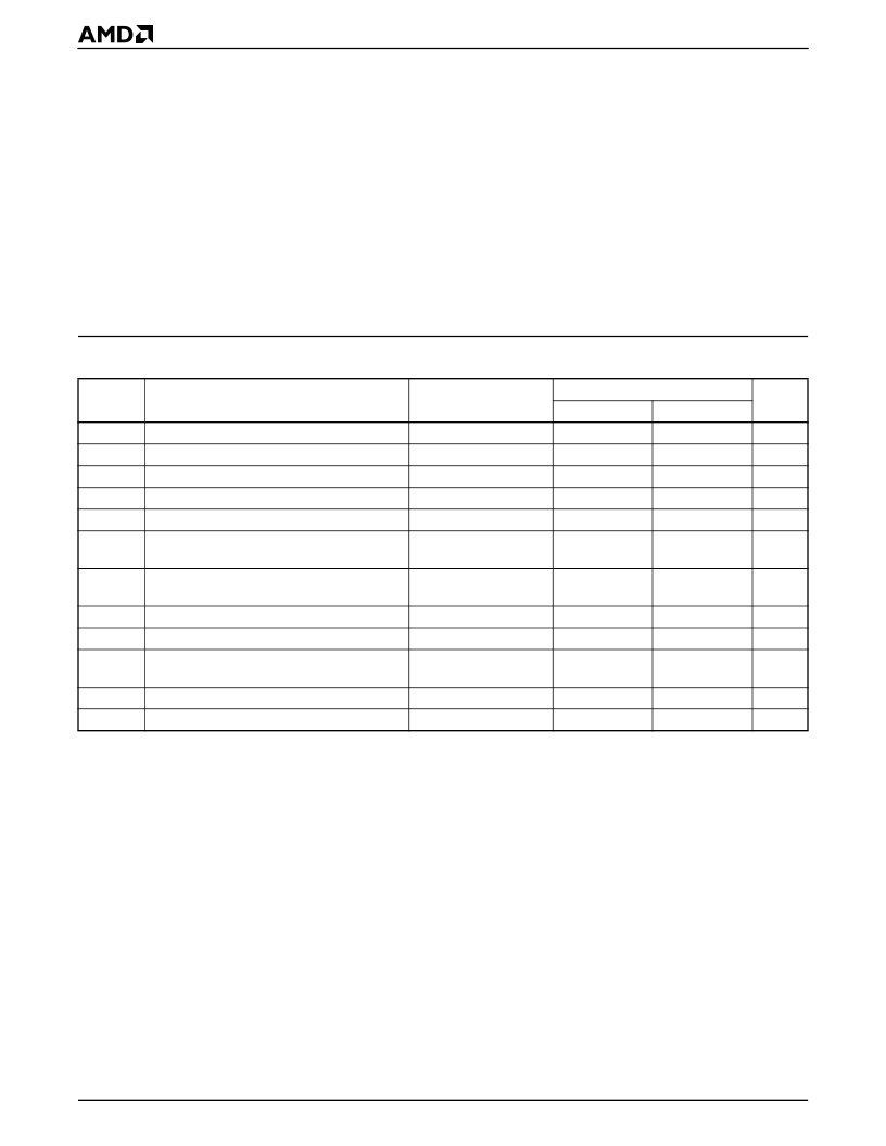
Symbol Parameter Description
V
IL
Input Low Voltage
V
IH
Input High Voltage
V
IH
Clock Input High Voltage (X2, X1)
V
OL
Output Low Voltage
V
OH
Output High Voltage
Notes
Min
–0.3
2.0
Max
0.8
Unit
V
V
V
V
V
mA/
MHz
V
CC
+ 2.6
V
CC
0.45
I
OL
= 4.0 mA
I
OH
= –1.0 mA
2.4
I
CC
Power Supply Current
Note 8
5.0
I
LI
Input Leakage Current
Note 1
Note 2
Note 3
Note 4
Note 5
Note 6
C
=1 MHz (Note 7)
C
=1 MHz (Note 7)
±
15
±
50
200
–400
±
15
±
50
10
14
μ
A
I
IH
I
IL
Input Leakage Current
Input Leakage Current
μ
A
μ
A
I
LO
Output Leakage Current
μ
A
C
IN
C
OUT
Input Capacitance
I/O Capacitance
pF
pF
相關(guān)PDF資料 |
PDF描述 |
|---|---|
| AM20E-2402SC | 20 watt dc-dc converters |
| AM20E-2403SC | 20 watt dc-dc converters |
| AM20E-2405SC | 20 watt dc-dc converters |
| AM20E-4802SC | 20 watt dc-dc converters |
| AM20E-4803SC | 20 watt dc-dc converters |
相關(guān)代理商/技術(shù)參數(shù) |
參數(shù)描述 |
|---|---|
| AM188ER-25KI/W | 制造商:未知廠家 制造商全稱:未知廠家 功能描述:16-Bit Microprocessor |
| AM188ER-25KIW | 制造商:Advanced Micro Devices 功能描述:MCU 16-bit E86 CISC ROMLess 3.3V 100-Pin PQFP 制造商:AMD (Advanced Micro Devices) 功能描述:MCU 16-bit E86 CISC ROMLess 3.3V 100-Pin PQFP |
| AM188ER-25VC/W | 制造商:未知廠家 制造商全稱:未知廠家 功能描述:16-Bit Microprocessor |
| AM188ER-25VCW | 制造商:AMD 制造商全稱:Advanced Micro Devices 功能描述:High-Performance, 80C186- and 80C188-Compatible, 16-Bit Embedded Microcontrollers with RAM |
| AM188ER-25VD\\W | 制造商:Advanced Micro Devices 功能描述: |
發(fā)布緊急采購(gòu),3分鐘左右您將得到回復(fù)。