- 您現(xiàn)在的位置:買賣IC網(wǎng) > PDF目錄378045 > PCI6515ZHK (Texas Instruments, Inc.) SINGLE SOCKET CARDBUS CONTROLLER WITH DEDICATED SMART CARD SOCKET PDF資料下載
參數(shù)資料
| 型號(hào): | PCI6515ZHK |
| 廠商: | Texas Instruments, Inc. |
| 英文描述: | SINGLE SOCKET CARDBUS CONTROLLER WITH DEDICATED SMART CARD SOCKET |
| 中文描述: | 單插槽CardBus控制器,專用智能卡插槽 |
| 文件頁(yè)數(shù): | 73/148頁(yè) |
| 文件大?。?/td> | 760K |
| 代理商: | PCI6515ZHK |
第1頁(yè)第2頁(yè)第3頁(yè)第4頁(yè)第5頁(yè)第6頁(yè)第7頁(yè)第8頁(yè)第9頁(yè)第10頁(yè)第11頁(yè)第12頁(yè)第13頁(yè)第14頁(yè)第15頁(yè)第16頁(yè)第17頁(yè)第18頁(yè)第19頁(yè)第20頁(yè)第21頁(yè)第22頁(yè)第23頁(yè)第24頁(yè)第25頁(yè)第26頁(yè)第27頁(yè)第28頁(yè)第29頁(yè)第30頁(yè)第31頁(yè)第32頁(yè)第33頁(yè)第34頁(yè)第35頁(yè)第36頁(yè)第37頁(yè)第38頁(yè)第39頁(yè)第40頁(yè)第41頁(yè)第42頁(yè)第43頁(yè)第44頁(yè)第45頁(yè)第46頁(yè)第47頁(yè)第48頁(yè)第49頁(yè)第50頁(yè)第51頁(yè)第52頁(yè)第53頁(yè)第54頁(yè)第55頁(yè)第56頁(yè)第57頁(yè)第58頁(yè)第59頁(yè)第60頁(yè)第61頁(yè)第62頁(yè)第63頁(yè)第64頁(yè)第65頁(yè)第66頁(yè)第67頁(yè)第68頁(yè)第69頁(yè)第70頁(yè)第71頁(yè)第72頁(yè)當(dāng)前第73頁(yè)第74頁(yè)第75頁(yè)第76頁(yè)第77頁(yè)第78頁(yè)第79頁(yè)第80頁(yè)第81頁(yè)第82頁(yè)第83頁(yè)第84頁(yè)第85頁(yè)第86頁(yè)第87頁(yè)第88頁(yè)第89頁(yè)第90頁(yè)第91頁(yè)第92頁(yè)第93頁(yè)第94頁(yè)第95頁(yè)第96頁(yè)第97頁(yè)第98頁(yè)第99頁(yè)第100頁(yè)第101頁(yè)第102頁(yè)第103頁(yè)第104頁(yè)第105頁(yè)第106頁(yè)第107頁(yè)第108頁(yè)第109頁(yè)第110頁(yè)第111頁(yè)第112頁(yè)第113頁(yè)第114頁(yè)第115頁(yè)第116頁(yè)第117頁(yè)第118頁(yè)第119頁(yè)第120頁(yè)第121頁(yè)第122頁(yè)第123頁(yè)第124頁(yè)第125頁(yè)第126頁(yè)第127頁(yè)第128頁(yè)第129頁(yè)第130頁(yè)第131頁(yè)第132頁(yè)第133頁(yè)第134頁(yè)第135頁(yè)第136頁(yè)第137頁(yè)第138頁(yè)第139頁(yè)第140頁(yè)第141頁(yè)第142頁(yè)第143頁(yè)第144頁(yè)第145頁(yè)第146頁(yè)第147頁(yè)第148頁(yè)
415
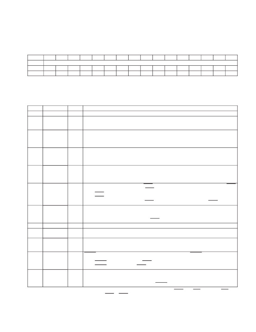
4.25 Bridge Control Register
The bridge control register provides control over various PCI6515 bridging functions. See Table 47 for a complete
description of the register contents.
Bit
Name
Type
Default
15
14
13
12
11
10
9
8
7
6
5
4
3
2
1
0
Bridge control
RW
1
R
0
R
0
R
0
R
0
R
0
RW
0
RW
1
RW
0
RW
1
RW
0
R
0
RW
0
RW
0
RW
0
RW
0
Register:
Offset:
Type:
Default:
Bridge control
3Eh (Function 0)
Read-only, Read/Write
0340h
Table 47. Bridge Control Register Description
BIT
1511
SIGNAL
RSVD
TYPE
R
FUNCTION
These bits return 0s when read.
Write posting enable. Enables write posting to and from the CardBus socket. Write posting enables the
posting of write data on burst cycles. Operating with write posting disabled impairs performance on burst
cycles. Note that burst write data can be posted, but various write transactions may not.
Memory window 1 type. This bit specifies whether or not memory window 1 is prefetchable. This bit is
encoded as:
0 = Memory window 1 is nonprefetchable.
1 = Memory window 1 is prefetchable (default).
Memory window 0 type. This bit specifies whether or not memory window 0 is prefetchable. This bit is
encoded as:
0 = Memory window 0 is nonprefetchable.
1 = Memory window 0 is prefetchable (default).
PCI interrupt IREQ routing enable. This bit is used to select whether PC Card functional interrupts are
routed to PCI interrupts or to the IRQ specified in the ExCA registers.
0 = Functional interrupts are routed to PCI interrupts (default).
1 = Functional interrupts are routed by ExCA registers.
CardBus reset. When this bit is set, the CRST signal is asserted on the CardBus interface. The CRST
signal can also be asserted by passing a PRST assertion to CardBus.
0 = CRST is deasserted.
1 = CRST is asserted (default).
This bit is not cleared by the assertion of PRST. It is only cleared by the assertion of GRST.
Master abort mode. This bit controls how the PCI6515 controller responds to a master abort when the
PCI6515 controller is an initiator on the CardBus interface.
0 = Master aborts not reported (default).
1 = Signal target abort on PCI and signal SERR, if enabled.
This bit returns 0 when read.
VGA enable. This bit affects how the PCI6515 controller responds to VGA addresses. When this bit is set,
accesses to VGA addresses are forwarded.
ISA mode enable. This bit affects how the PCI6515 controller passes I/O cycles within the 64-Kbyte ISA
range. When this bit is set, the PCI6515 controller does not forward the last 768 bytes of each 1K I/O range
to CardBus.
CSERR enable. This bit controls the response of the PCI6515 controller to CSERR signals on the CardBus
bus.
0 = CSERR is not forwarded to PCI SERR (default)
1 = CSERR is forwarded to PCI SERR.
CardBus parity error response enable. This bit controls the response of the PCI6515 to CardBus parity
errors.
0 = CardBus parity errors are ignored (default).
1 = CardBus parity errors are reported using CPERR.
10
POSTEN
RW
9
PREFETCH1
RW
8
PREFETCH0
RW
7
INTR
RW
6
CRST
RW
5
MABTMODE
RW
4
RSVD
R
3
VGAEN
RW
2
ISAEN
RW
1
CSERREN
RW
0
CPERREN
RW
One or more bits in this register are PME context bits and can be cleared only by the assertion of GRST when PME is enabled. If PME is not
enabled, then this bit is cleared by the assertion of PRST or GRST.
相關(guān)PDF資料 |
PDF描述 |
|---|---|
| PCI7610LQFP | PC Card, UltraMedia, and Integrated 1394a-2000 OHCI Two-Port PHY/Link-Layer Controller |
| PCM1712U | Stereo Audio Digital-To-Analog Converter(立體聲音頻D\A轉(zhuǎn)換器) |
| PCM1715U | Dual Voltage Output CMOS Delta-Sigma Digital-To-Analog Converter With On-Chip Digital Filter(帶片內(nèi)濾波的雙路電壓輸出CMOS ΔΣD\A轉(zhuǎn)換器) |
| PCM1726 | Stereo Audio Digital-To-Analog Converter 16 Bits, 96kHz Sampling(16位96kHz采樣率立體聲音頻D\A轉(zhuǎn)換器) |
| PCM3008T2K | LOW POWER AND LOW VOLTAGE 16-BIT, SINGLE-ENDED ANALOG INPUT/OUTPUT STEREO AUDIO CODEC |
相關(guān)代理商/技術(shù)參數(shù) |
參數(shù)描述 |
|---|---|
| PCI6520 | 制造商:PLX 制造商全稱:PLX 功能描述:Transparent FastLane⑩ PCI-X -to- PCI-X Bridge |
| PCI6520-CB13BI | 功能描述:外圍驅(qū)動(dòng)器與原件 - PCI PCIX to PCIX BRIDGE 64bit 133MHz RoHS:否 制造商:PLX Technology 工作電源電壓: 最大工作溫度: 安裝風(fēng)格:SMD/SMT 封裝 / 箱體:FCBGA-1156 封裝:Tray |
| PCI6520-CB13BI G | 功能描述:外圍驅(qū)動(dòng)器與原件 - PCI PCIX to PCIX Bridge 64Bit 133MHz RoHS:否 制造商:PLX Technology 工作電源電壓: 最大工作溫度: 安裝風(fēng)格:SMD/SMT 封裝 / 箱體:FCBGA-1156 封裝:Tray |
| PCI6520-XX13BC | 制造商:PLX 制造商全稱:PLX 功能描述:Transparent FastLane⑩ PCI-X -to- PCI-X Bridge |
| PCI6540 | 制造商:PLX 制造商全稱:PLX 功能描述:Dual-Mode (Transparent & Non-Transparent) Universal FastLane⑩ PCI-X -to- PCI-X Bridge |
發(fā)布緊急采購(gòu),3分鐘左右您將得到回復(fù)。