- 您現(xiàn)在的位置:買賣IC網(wǎng) > PDF目錄375989 > FW82801E (Intel Corp.) Intel 82801E Communications I/O Controller Hub (C-ICH) PDF資料下載
參數(shù)資料
| 型號(hào): | FW82801E |
| 廠商: | Intel Corp. |
| 英文描述: | Intel 82801E Communications I/O Controller Hub (C-ICH) |
| 中文描述: | 英特爾82801E通訊I / O控制器集線器(丙,出血) |
| 文件頁(yè)數(shù): | 40/84頁(yè) |
| 文件大小: | 1196K |
| 代理商: | FW82801E |
第1頁(yè)第2頁(yè)第3頁(yè)第4頁(yè)第5頁(yè)第6頁(yè)第7頁(yè)第8頁(yè)第9頁(yè)第10頁(yè)第11頁(yè)第12頁(yè)第13頁(yè)第14頁(yè)第15頁(yè)第16頁(yè)第17頁(yè)第18頁(yè)第19頁(yè)第20頁(yè)第21頁(yè)第22頁(yè)第23頁(yè)第24頁(yè)第25頁(yè)第26頁(yè)第27頁(yè)第28頁(yè)第29頁(yè)第30頁(yè)第31頁(yè)第32頁(yè)第33頁(yè)第34頁(yè)第35頁(yè)第36頁(yè)第37頁(yè)第38頁(yè)第39頁(yè)當(dāng)前第40頁(yè)第41頁(yè)第42頁(yè)第43頁(yè)第44頁(yè)第45頁(yè)第46頁(yè)第47頁(yè)第48頁(yè)第49頁(yè)第50頁(yè)第51頁(yè)第52頁(yè)第53頁(yè)第54頁(yè)第55頁(yè)第56頁(yè)第57頁(yè)第58頁(yè)第59頁(yè)第60頁(yè)第61頁(yè)第62頁(yè)第63頁(yè)第64頁(yè)第65頁(yè)第66頁(yè)第67頁(yè)第68頁(yè)第69頁(yè)第70頁(yè)第71頁(yè)第72頁(yè)第73頁(yè)第74頁(yè)第75頁(yè)第76頁(yè)第77頁(yè)第78頁(yè)第79頁(yè)第80頁(yè)第81頁(yè)第82頁(yè)第83頁(yè)第84頁(yè)

Intel
82801E C-ICH
40
Advance Information Datasheet
3.2.6
IDE Interface
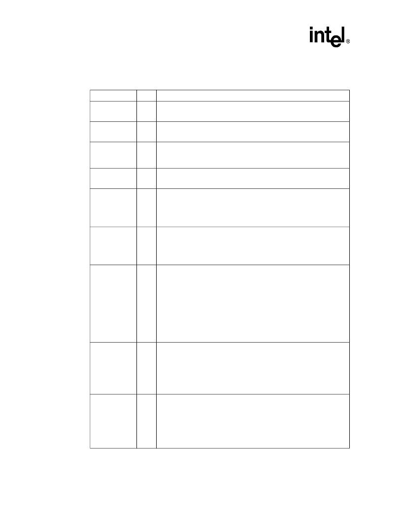
Table 12. IDE Interface Signals
Name
Type
Description
PDCS1#
SDCS1#
O
Primary and Secondary IDE Device Chip Selects for 100 Range:
These
signals are for the ATA command register block. This output signal is connected
to the corresponding signal on the primary or secondary IDE connector.
Primary and Secondary IDE Device Chip Select for 300 Range:
These signals
are for the ATA control register block. This output signal is connected to the
corresponding signal on the primary or secondary IDE connector.
Primary and Secondary IDE Device Address:
These output signals are
connected to the corresponding signals on the primary or secondary IDE
connectors. They are used to indicate which byte in either the ATA command
block or control block is being addressed.
Primary and Secondary IDE Device Data:
These signals directly drive the
corresponding signals on the primary or secondary IDE connector. There is a
weak internal pull-down resistor on PDD[7] and SDD[7].
Primary and Secondary IDE Device DMA Request:
These input signals are
directly driven from the DRQ signals on the primary or secondary IDE connector.
It is asserted by the IDE device to request a data transfer, and used in
conjunction with the PCI bus master IDE function. They are not associated with
any AT-compatible DMA channel. There is a weak internal pull-down resistor on
these signals.
Primary and Secondary IDE Device DMA Acknowledge:
These signals
directly drive the DAK# signals on the primary and secondary IDE connectors.
Each signal is asserted by the 82801E C-ICH to indicate to the IDE DMA slave
devices that a given data transfer cycle (assertion of DIOR# or DIOW#) is a DMA
data transfer cycle. This signal is used in conjunction with the PCI bus master
IDE function and are not associated with any AT-compatible DMA channel.
Primary and Secondary Disk I/O Read (PIO and Non-Ultra DMA):
This is the
command to the IDE device that it may drive data on the PDD or SDD lines. Data
is latched by the 82801E C-ICH on the deassertion edge of PDIOR# or SDIOR#.
The IDE device is selected either by the ATA register file chip selects (PDCS1# or
SDCS1#, PDCS3# or SDCS3#) and the PDA or SDA lines, or the IDE DMA
acknowledge (PDDAK# or SDDAK#).
Primary and Secondary Disk Write Strobe (Ultra DMA Writes to Disk):
This is
the data write strobe for writes to disk. When writing to disk, 82801E C-ICH drives
valid data on rising and falling edges of PDWSTB or SDWSTB.
Primary and Secondary Disk DMA Ready (Ultra DMA Reads from Disk):
This
is the DMA ready for reads from disk. When reading from disk, 82801E C-ICH
deasserts PRDMARDY# or SRDMARDY# to pause burst data transfers.
Primary and Secondary Disk I/O Write (PIO and Non-Ultra DMA):
This is the
command to the IDE device that it may latch data from the PDD or SDD lines.
Data is latched by the IDE device on the deassertion edge of PDIOW# or
SDIOW#. The IDE device is selected either by the ATA register file chip selects
(PDCS1# or SDCS1#, PDCS3# or SDCS3#) and the PDA or SDA lines, or the
IDE DMA acknowledge (PDDAK# or SDDAK#).
Primary and Secondary Disk Stop (Ultra DMA):
82801E C-ICH asserts this
signal (PDSTOP, SDSTOP) to terminate a burst.
Primary and Secondary I/O Channel Ready (PIO):
This signal keeps the strobe
active (PDIOR# or SDIOR# on reads, PDIOW# or SDIOW# on writes) longer than
the minimum width. It adds wait states to PIO transfers.
Primary and Secondary Disk Read Strobe (Ultra DMA Reads from Disk)
:
When reading from disk, 82801E C-ICH latches data on rising and falling edges
of this signal from the disk.
Primary and Secondary Disk DMA Ready (Ultra DMA Writes to Disk)
: When
writing to disk, this is deasserted by the disk to pause burst data transfers.
PDCS3#
SDCS3#
O
PDA[2:0]
SDA[2:0]
O
PDD[15:0]
SDD[15:0]
I/O
PDDREQ
SDDREQ
I
PDDACK#
SDDACK#
O
PDIOR#
/(PDWSTB
/PRDMARDY#)
SDIOR#
/(SDWSTB
/SRDMARDY#)
O
PDIOW#
/(PDSTOP)
SDIOW#
/(SDSTOP)
O
PIORDY
/(PDRSTB
/PWDMARDY#)
SIORDY
/(SDRSTB
/SWDMARDY#)
I
相關(guān)PDF資料 |
PDF描述 |
|---|---|
| FWB150 | 1.5 AMP FAST RECOVERY BRIDGE RECTIFIERS |
| FWB151 | 1.5 AMP FAST RECOVERY BRIDGE RECTIFIERS |
| FWB1510 | 1.5 AMP FAST RECOVERY BRIDGE RECTIFIERS |
| FWB152 | 1.5 AMP FAST RECOVERY BRIDGE RECTIFIERS |
| FWB154 | 1.5 AMP FAST RECOVERY BRIDGE RECTIFIERS |
相關(guān)代理商/技術(shù)參數(shù) |
參數(shù)描述 |
|---|---|
| FW82801E S L5AW | 制造商:Intel 功能描述:I/O Controller Phase Controller 421-Pin BGA |
| FW82801EB | 制造商:Rochester Electronics LLC 功能描述:- Bulk |
| FW82801EB S L6TN | 制造商:Intel 功能描述:CONTROLLER: IO CONTROLLER |
| FW82801EB S L73Z | 制造商:Intel 功能描述:I/O Controller Phase Controller 460-Pin BGA |
| FW82801ER | 制造商:Rochester Electronics LLC 功能描述:- Bulk |
發(fā)布緊急采購(gòu),3分鐘左右您將得到回復(fù)。