- 您現在的位置:買賣IC網 > PDF目錄69040 > MSX340PB480 (FAIRCHILD SEMICONDUCTOR CORP) DSP-CROSSBAR SWITCH, PBGA480 PDF資料下載
參數資料
| 型號: | MSX340PB480 |
| 廠商: | FAIRCHILD SEMICONDUCTOR CORP |
| 元件分類: | 數字信號處理外設 |
| 英文描述: | DSP-CROSSBAR SWITCH, PBGA480 |
| 封裝: | 37.50 X 37.50 MM, 1.27 MM PITCH, MO-149, TBGA-480 |
| 文件頁數: | 32/33頁 |
| 文件大小: | 651K |
| 代理商: | MSX340PB480 |
第1頁第2頁第3頁第4頁第5頁第6頁第7頁第8頁第9頁第10頁第11頁第12頁第13頁第14頁第15頁第16頁第17頁第18頁第19頁第20頁第21頁第22頁第23頁第24頁第25頁第26頁第27頁第28頁第29頁第30頁第31頁當前第32頁第33頁
Preliminary
www.fairchildsemi.com
8
M
SX340
Introduction (Continued)
Control Signals
Every port on the MSX340 has two available global clock
inputs, input enables, and output enables. However, not all
ports have access to the same global control signals.
There are four global clocks (CLK_0 through CLK_3), four
global input enables (IE_0 through IE_3), and four global
output enables (OE_0 through OE_3). Each global control
signal is available to half of the ports on the MSX device.
Table 2 below shows the global control signals that are
available to each port.
TABLE 2. MSX Global Control Signals
RapidConfigure Interface
The MSX340 can be configured in either of two ways. Both
the JTAG serial programming interface and the RapidCon-
figure (RC) parallel interface can assign crosspoint connec-
tions and configure I/O buffers, but JTAG is a serial input
and is slower. JTAG runs reliably up to 8 MHz and requires
over twenty cycles to program a single command. The
RapidConfigure interface can run at up to 40 MHz and can
send a new command on every clock cycle. Systems
requiring frequent reconfiguration should be designed to
use the RapidConfigure interface.
RapidConfigure is a 29 signal parallel interface that effec-
tively flattens the serial JTAG bitstream. Rather than con-
secutively shifting in twenty or so bits of data to configure
an I/O buffer or make a crosspoint connection, all of these
bits are driven on the RC lines simultaneously and then
latched in by the MSX340 in a single cycle. Additionally, the
MSX RapidConfigure interface has been enhanced to
enable reading back of configuration data from the device.
Signal Description
The RC interface supports four types of operations. Two
are write operations to the MSX (I/O buffer configuration or
crosspoint programming) and two are read operations (I/O
buffer and crosspoint configuration read). The RC signals
serve different purposes depending upon the type of oper-
ation being performed.
Most of the signals on the MSX340’s RC interface are bi-
directional. These signals receive data during write opera-
tions. During read operations these pins receive data dur-
ing the first part of the cycle, and then drive the interface in
the final part of the cycle. RCA[9:0], RCB[9:0], and RCC[0]
are bi-directional pins. RCC[3:1], RC_CLK, RC_EN, and
RCI[1:0] are dedicated inputs. RC_RDY is a dedicated out-
put.
The RC_CLK signal is the strobe that latches write data
into the MSX340. It synchronizes the signals driven on to
the RC interface and determines the rate at which com-
mands can be loaded into the MSX340. The MSX340
latches command data on the falling edge of RC_CLK
when RC_EN is asserted. RC Write operations can be
repeated on consecutive clocks simply by keeping the
RC_EN signal asserted and providing new commands on
the RCA, RCB, RCC, and RCI signals. RC Read opera-
tions require four AC clock cycles and cannot be performed
on back-to-back clocks.
RC_EN is an Active LOW signal that enables an RC opera-
tion. Back-to-back RC Write operations may be performed
by keeping the RC_EN signal asserted. During RC Read
operations RC_EN must remain asserted until the cycle is
complete. Back-to-back RC Read operations can be exe-
cuted simply by keeping RC_EN asserted.
The MSX340 asserts RC_RDY when it has entered the
final stage of a read and data out is ready. RC_RDY is
asserted on the falling edge of RC_CLK, and de-asserted
on the next falling edge. The MSX340 will be driving valid
read data on the RC interface when RC_RDY is asserted
HIGH.
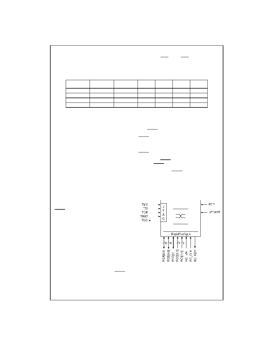
FIGURE 4. MSX Switch Configuration Signals
The RC interface specifies that the RCI signals be used to
determine the type of operation being performed.
MSX340 Port
Number
Input/Output
Clock Source 1
Input Output
Clock Source 2
Input
Enable 1
Input
Enable 2
Output
Enable 1
Output
Enable 2
Ports 0-84
CLK_0
CLK_1
IE_0
IE_1
OE_0
OE_1
Ports 85-169
CLK_1
CLK_2
IE_1
IE_2
OE_1
OE_2
Ports 170-254
CLK_2
CLK_3
IE_2
IE_3
OE_2
OE_3
Ports 255-339
CLK_3
CLK_0
IE_3
IE_0
OE_3
OE_0
RCA[9:0]
= RapidConfigure Address A
RCB[9:0]
= RapidConfigure Address B
RCC[3:0]
= RapidConfigure Program Variable C
RCI[1:0]
= RapidConfigure Instruction Bits
RC_CLK
= RapidConfigure Clock
RC_EN
= RapidConfigure Cycle Enable
RC_RDY
= Read out I/O buffer and connect/disconnect
status
相關PDF資料 |
PDF描述 |
|---|---|
| MSX532-TB792 | DSP-CROSSBAR SWITCH, PBGA792 |
| MSX340-PB480 | DSP-CROSSBAR SWITCH, PBGA480 |
| MT5TL8L32T-40IT | SPECIALTY MICROPROCESSOR CIRCUIT, PQFP100 |
| MT5TL8L32T-50IT | SPECIALTY MICROPROCESSOR CIRCUIT, PQFP100 |
| MT5TL8L32T-70IT | SPECIALTY MICROPROCESSOR CIRCUIT, PQFP100 |
相關代理商/技術參數 |
參數描述 |
|---|---|
| MSX4541 | 制造商:Cinch Connectors 功能描述: |
| MSX4542 | 制造商:Cinch Connectors 功能描述: |
| MSX-50 | 制造商:未知廠家 制造商全稱:未知廠家 功能描述:Photovoltaic Modules |
| MSX532 | 制造商:FAIRCHILD 制造商全稱:Fairchild Semiconductor 功能描述:532 Port Digital Crosspoint Switch with LVTTL I/O’s |
| MSX532 WAF | 制造商:Fairchild Semiconductor Corporation 功能描述: |
發(fā)布緊急采購,3分鐘左右您將得到回復。