- 您現(xiàn)在的位置:買賣IC網(wǎng) > PDF目錄367908 > pentium III (Intel Corp.) pentium III Processor for the PGA370 Socket at 500MHz to 933MHz(工作頻率500到933兆赫茲活動(dòng)帶PGA370插孔奔III處理器) PDF資料下載
參數(shù)資料
| 型號(hào): | pentium III |
| 廠商: | Intel Corp. |
| 英文描述: | pentium III Processor for the PGA370 Socket at 500MHz to 933MHz(工作頻率500到933兆赫茲活動(dòng)帶PGA370插孔奔III處理器) |
| 中文描述: | 奔騰III處理器在500MHz到933MHz的(工作頻率500到933兆赫茲活動(dòng)帶PGA370插孔奔三處理器的PGA370插座) |
| 文件頁(yè)數(shù): | 22/78頁(yè) |
| 文件大?。?/td> | 610K |
| 代理商: | PENTIUM III |
第1頁(yè)第2頁(yè)第3頁(yè)第4頁(yè)第5頁(yè)第6頁(yè)第7頁(yè)第8頁(yè)第9頁(yè)第10頁(yè)第11頁(yè)第12頁(yè)第13頁(yè)第14頁(yè)第15頁(yè)第16頁(yè)第17頁(yè)第18頁(yè)第19頁(yè)第20頁(yè)第21頁(yè)當(dāng)前第22頁(yè)第23頁(yè)第24頁(yè)第25頁(yè)第26頁(yè)第27頁(yè)第28頁(yè)第29頁(yè)第30頁(yè)第31頁(yè)第32頁(yè)第33頁(yè)第34頁(yè)第35頁(yè)第36頁(yè)第37頁(yè)第38頁(yè)第39頁(yè)第40頁(yè)第41頁(yè)第42頁(yè)第43頁(yè)第44頁(yè)第45頁(yè)第46頁(yè)第47頁(yè)第48頁(yè)第49頁(yè)第50頁(yè)第51頁(yè)第52頁(yè)第53頁(yè)第54頁(yè)第55頁(yè)第56頁(yè)第57頁(yè)第58頁(yè)第59頁(yè)第60頁(yè)第61頁(yè)第62頁(yè)第63頁(yè)第64頁(yè)第65頁(yè)第66頁(yè)第67頁(yè)第68頁(yè)第69頁(yè)第70頁(yè)第71頁(yè)第72頁(yè)第73頁(yè)第74頁(yè)第75頁(yè)第76頁(yè)第77頁(yè)第78頁(yè)
22
Datasheet
Pentium
III Processor for the PGA370 Socket at 500 MHz to 933 MHz
2.9
Test Access Port (TAP) Connection
Due to the voltage levels supported by other components in the Test Access Port (TAP) logic, it is
recommended that the processor be the first in the TAP chain and followed by any other
components within the system. A translation buffer should be used to connect the rest of the chain
unless one of the other components is capable of accepting a 1.5V input. Similar considerations
must be made for TCK, TMS, and TRST# signals.
In a two-way MP system design, be cautious when including an empty PGA370 socket in the scan
chain. All sockets in the scan chain must have a processor installed to complete the chain or the
system must support a method to bypass the empty socket; PGA370 termination packages should
not connect TDI to TDO in order to avoid placing the TDO pull-up resistor in parallel.
2.10
Maximum Ratings
Table 5
contains processor stress ratings only. Functional operation at the absolute maximum and
minimum is not implied nor guaranteed. The processor should not receive a clock while subjected
to these conditions. Functional operating conditions are given in the AC and DC tables in
Section 2.11
through
Section 2.13
. Extended exposure to the maximum ratings may affect device
reliability. Furthermore, although the processor contains protective circuitry to resist damage from
static electric discharge, one should always take precautions to avoid high static voltages or electric
fields.
NOTES:
1. Input voltage can never exceed V
SS
+ 2.18 volts.
2. Input voltage can never go below V
TT
- 2.18 volts.
3. Parameter applies to CMOS (except BCLK, PICCLK, and PWRGOOD), APIC, and TAP bus signal groups
only.
4. Parameter applies to CMOS signals BCLK, PICCLK, and PWRGOOD only.
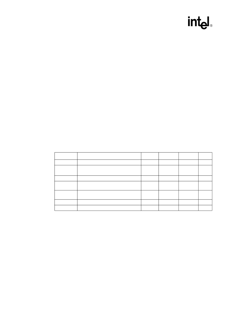
Table 5. Absolute Maximum Ratings
Symbol
Parameter
Min
Max
Unit
Notes
T
STORAGE
Processor storage temperature
–40
85
°C
V
CC
CORE
and
V
TT
Processor core voltage and termination
supply voltage with respect to V
SS
–0.5
2.1
V
V
in
AGTL
AGTL+ buffer input voltage
V
TT
- 2.18
2.18
V
1, 2
V
in
CMOS
1.5
CMOS buffer DC input voltage with respect
to V
SS
V
TT
- 2.18
2.18
V
1, 2, 3
V
in
CMOS
2.5
CMOS buffer DC input voltage with respect
to V
SS
-0.58
3.18
V
4
I
VID
Max VID pin current
5
mA
I
CPUPRES#
Max CPUPRES# pin current
5
mA
相關(guān)PDF資料 |
PDF描述 |
|---|---|
| pentium II | pentium II processor With On-die Cache Mobile Module Connector 1 (MMC-1)(帶緩存和連接器1的奔II處理器) |
| PERICOMPI7C8150 | 2-Port PCI-to-PCI Bridge |
| PESDXL2BT | Low capacitance double bidirectional ESD protection diodes in SOT23 |
| PESDXL2UM | LJT 23C 21#20 2#16 PIN RECP |
| PETAM1270BK300R | BRAID SLEEVING 300M |
相關(guān)代理商/技術(shù)參數(shù) |
參數(shù)描述 |
|---|---|
| P-ENV568K3G3 | 制造商:Panasonic Industrial Company 功能描述:TUNER |
| PEO14012 | 制造商:TE Connectivity 功能描述:RELAY SPCO 12VDC |
| PEO14024 | 制造商:TE Connectivity 功能描述:RELAY SPCO 24VDC |
| PEO96742 | 制造商:Delphi Corporation 功能描述:ASM TERM |
| PEOODO3A | 制造商:MACOM 制造商全稱:Tyco Electronics 功能描述:Versatile Power Entry Module with Small Footprint |
發(fā)布緊急采購(gòu),3分鐘左右您將得到回復(fù)。