- 您現(xiàn)在的位置:買賣IC網(wǎng) > PDF目錄359412 > VPX3224D (Electronic Theatre Controls, Inc.) Video Pixel Decoders PDF資料下載
參數(shù)資料
| 型號: | VPX3224D |
| 廠商: | Electronic Theatre Controls, Inc. |
| 英文描述: | Video Pixel Decoders |
| 中文描述: | 視頻解碼器像素 |
| 文件頁數(shù): | 82/92頁 |
| 文件大小: | 672K |
| 代理商: | VPX3224D |
第1頁第2頁第3頁第4頁第5頁第6頁第7頁第8頁第9頁第10頁第11頁第12頁第13頁第14頁第15頁第16頁第17頁第18頁第19頁第20頁第21頁第22頁第23頁第24頁第25頁第26頁第27頁第28頁第29頁第30頁第31頁第32頁第33頁第34頁第35頁第36頁第37頁第38頁第39頁第40頁第41頁第42頁第43頁第44頁第45頁第46頁第47頁第48頁第49頁第50頁第51頁第52頁第53頁第54頁第55頁第56頁第57頁第58頁第59頁第60頁第61頁第62頁第63頁第64頁第65頁第66頁第67頁第68頁第69頁第70頁第71頁第72頁第73頁第74頁第75頁第76頁第77頁第78頁第79頁第80頁第81頁當前第82頁第83頁第84頁第85頁第86頁第87頁第88頁第89頁第90頁第91頁第92頁
PRELIMINARY DATA SHEET
VPX 3225D, VPX 3224D
82
Micronas
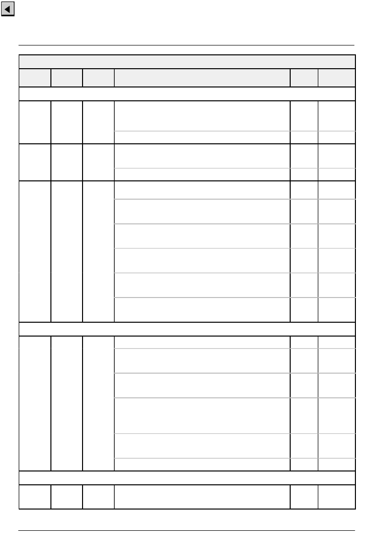
FP-RAM VPX Back-End
Name
Default
Function
Mode
Number
of Bits
Address
Hex
HVREF
h’151
12
w
Start position of the programmable ‘video active’
The start position has to be an even value and is given relative to the
trailing edge of HREF. Programmable VACT is activated with bit [2] of
the control word (h’140)!
40
pval_
start
bit [10:0]: start of VACT reference signal
h’152
12
w
End position of the programmable ‘video active’
The end position has to be an even value and is given relative to the
trailing edge of HREF.
720
pval_stop
bit [10:0]: end of VACT reference signal
h’153
12
w
HREF and VREF control
determines length and polarity of the timing reference signals
refsig
bit [0]:
Odd/Even polarity
0
odd high
1
even high
0
oepol
bit [1]:
HREF Polarity
0
active high
1
active low
0
hpol
bit [2]:
VREF Polarity
0
active high
1
active low
0
vpol
bit [5:3]:
VREF pulse width, binary value + 2
000:pulse width = 2
111: pulse width = 9
0
vlen
bit [6]:
1 disables field as output
setting this bit will force the ‘field’ pin to the high impedance
state
0
disfield
Output Multiplexer
h’154
12
w
Output Multiplexer
0
outmux
bit [7:0]:
Multi-purpose bits on Port B
determines the state of Port B when used as programmable
output
bmp
bit [8]:
activate multi-purpose bits on Port B
note that double clock mode has to be selected for this
option!
bmpon
bit [9]:
Port Mode
0
parallel_out, ‘single clock’, Port A & B = FO[15:0];
1
‘double clock’
Port A = FO[15:8] / FO[7:0],
Port B = programmable output/not used;
double
bit [10]:
switch ‘VBI active’ qualifier
0
connect ‘VBI active’ to VACT pin
1
connect ‘VBI active’ to TDO pin
vbiact
bit [11]:
reserved (must be set to zero)
Temporal Decimation
h’157
12
w
Number of frames to output within 3000 frames
This value will be activated only if the corresponding latch flag is set
(control word h’140, bit [10] ).
3000
tdecframes
相關(guān)PDF資料 |
PDF描述 |
|---|---|
| VPX3224E | Video Pixel Decoders |
| VPX322XE | Video Pixel Decoders |
| VQ1000J | N-Channel Enhancement-Mode MOSFET Transistor(最小漏源擊穿電壓60V,夾斷電流0.225A的N溝道增強型MOSFET晶體管) |
| VQ1000J | N-Channel 60-V (D-S) MOSFET |
| VQ1001J | Dual N-Channel 30-V (D-S) MOSFET with Schottky Diode |
相關(guān)代理商/技術(shù)參數(shù) |
參數(shù)描述 |
|---|---|
| VPX3224D-C3 | 制造商:未知廠家 制造商全稱:未知廠家 功能描述:Microprocessor |
| VPX3224E | 制造商:MICRONAS 制造商全稱:MICRONAS 功能描述:Video Pixel Decoders |
| VPX3225D | 制造商:未知廠家 制造商全稱:未知廠家 功能描述:Video Pixel Decoders |
| VPX3225D-C3 | 制造商:未知廠家 制造商全稱:未知廠家 功能描述:Microprocessor |
| VPX3225E | 制造商:MICRONAS 制造商全稱:MICRONAS 功能描述:Video Pixel Decoders |
發(fā)布緊急采購,3分鐘左右您將得到回復(fù)。