- 您現(xiàn)在的位置:買賣IC網(wǎng) > PDF目錄377488 > IDT88P8344 (Integrated Device Technology, Inc.) SPI EXCHANGE 4 x SPI-3 TO SPI-4 Issue 1.0 PDF資料下載
參數(shù)資料
| 型號(hào): | IDT88P8344 |
| 廠商: | Integrated Device Technology, Inc. |
| 英文描述: | SPI EXCHANGE 4 x SPI-3 TO SPI-4 Issue 1.0 |
| 中文描述: | SPI交換4 ×的SPI - 3至SPI - 4期1.0 |
| 文件頁(yè)數(shù): | 76/98頁(yè) |
| 文件大小: | 601K |
| 代理商: | IDT88P8344 |
第1頁(yè)第2頁(yè)第3頁(yè)第4頁(yè)第5頁(yè)第6頁(yè)第7頁(yè)第8頁(yè)第9頁(yè)第10頁(yè)第11頁(yè)第12頁(yè)第13頁(yè)第14頁(yè)第15頁(yè)第16頁(yè)第17頁(yè)第18頁(yè)第19頁(yè)第20頁(yè)第21頁(yè)第22頁(yè)第23頁(yè)第24頁(yè)第25頁(yè)第26頁(yè)第27頁(yè)第28頁(yè)第29頁(yè)第30頁(yè)第31頁(yè)第32頁(yè)第33頁(yè)第34頁(yè)第35頁(yè)第36頁(yè)第37頁(yè)第38頁(yè)第39頁(yè)第40頁(yè)第41頁(yè)第42頁(yè)第43頁(yè)第44頁(yè)第45頁(yè)第46頁(yè)第47頁(yè)第48頁(yè)第49頁(yè)第50頁(yè)第51頁(yè)第52頁(yè)第53頁(yè)第54頁(yè)第55頁(yè)第56頁(yè)第57頁(yè)第58頁(yè)第59頁(yè)第60頁(yè)第61頁(yè)第62頁(yè)第63頁(yè)第64頁(yè)第65頁(yè)第66頁(yè)第67頁(yè)第68頁(yè)第69頁(yè)第70頁(yè)第71頁(yè)第72頁(yè)第73頁(yè)第74頁(yè)第75頁(yè)當(dāng)前第76頁(yè)第77頁(yè)第78頁(yè)第79頁(yè)第80頁(yè)第81頁(yè)第82頁(yè)第83頁(yè)第84頁(yè)第85頁(yè)第86頁(yè)第87頁(yè)第88頁(yè)第89頁(yè)第90頁(yè)第91頁(yè)第92頁(yè)第93頁(yè)第94頁(yè)第95頁(yè)第96頁(yè)第97頁(yè)第98頁(yè)
76
IDT88P8344 SPI EXCHANGE 4 x SPI-3 TO SPI-4
INDUSTRIAL TEMPERATURE RANGE
APRIL 10, 2006
timng register is used to manually align the phase of data lane n by adding from
0.1 clock cycle to 0.3 clock cycles of delay.
DTCn [1:0]
4 egress data lane n.
[1:0]=0=No added delay
[1:0]=1=Add 0.1 clock cycle of delay to data lane n
[1:0]=2=Add 0.2 clock cycles of delay to data lane n
[1:0]=3=Add 0.3 clock cycles of delay to data lane n
Used for adding 0.1 clock cycle units of output delay to SPI-
SPI-4 egress control lane timing register
(Block_base 0x0800 + Register_offset 0x2B)
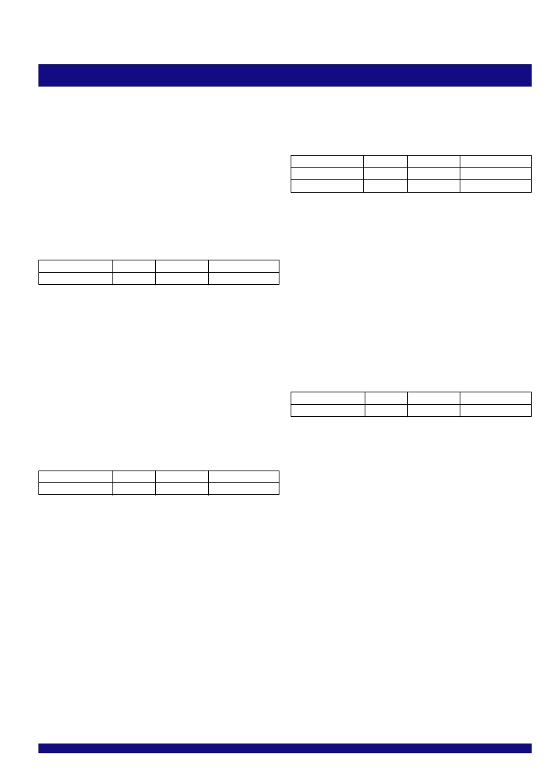
TABLE 115 - SPI-4 EGRESS CONTROL LANE
TIMING REGISTER (REGISTER_OFFSET 0x2B)
Field
Bits
CTLTC[1:0]
1:0
SPI-4 egress status timing register (Block_base
0x0800 + Register_offset 0x2D)
TABLE 117 - SPI-4 EGRESS STATUS TIMING
REGISTER (REGISTER_OFFSET 0x2D)
Field
Bits
STC0[1:0]
1:0
STC1[1:0]
3:2
The SPI-4 egress status clock timng register at Block_base 0x0800 +
Register_offset 0x2E has read and write access. The SPI-4 egress status clock
timng register is used to manually align the phase of the SPI-4 egress status clock
to the status outputs by adding from0.1 clock cycle to 0.9 clock cycles of delay
to the status clock output. Note that tap selection is not monotonic with the number
in bit field [3:0]. The SCTC[3:0] field is valid only for LVDS status, not for LVTTL
status.
SCTC [3:0]
4 egress status clock output.
[3:0]=0=No added delay
[3:0]=1=Add 0.1 clock cycle of delay t o the SPI-4 egress status clock
[3:0]=3=Add 0.2 clock cycles of delay to the SPI-4 egress status clock
[3:0]=2=Add 0.3 clock cycles of delay to the SPI-4 egress status clock
[3:0]=7=Add 0.4 clock cycles of delay to the SPI-4 egress status clock
[3:0]=6=Add 0.5 clock cycles of delay to the SPI-4 egress status clock
[3:0]=4=Add 0.6 clock cycles of delay to the SPI-4 egress status clock
[3:0]=5=Add 0.7 clock cycles of delay to the SPI-4 egress status clock
[3:0]=F=Add 0.8 clock cycles of delay to the SPI-4 egress status clock
[3:0]=E=Add 0.9 clock cycles of delay to the SPI-4 egress status clock
Used for adding 0.1 unit intervals of output delay to the SPI-
Length
2
Initial Value
0
TABLE 116 - SPI-4 EGRESS DATA CLOCK TIMING
REGISTER (REGISTER_OFFSET 0x2C)
Field
Bits
DCTC[3:0]
3:0
The SPI-4 egress data clock timng control register at Block_base 0x0800
has read and write access. The SPI-4 egress data clock timng control register
is used to manually align the phase of the SPI-4 egress data clock to the data
and control lanes by adding from0.1 clock cycle to 0.9 clock cycles of delay to
the data clock output. Note that tap selection is not monotonic with the number
in bit field [3:0].
Length
4
Initial Value
0
The SPI-4 egress control lane timng register at Block_base 0x0800 has read
and write access. The SPI-4 egress control lane timng register is used to
manually align the phase of the control lane by adding from0.1 clock cycle to
0.3 clock cycles of delay.
CTLTC [1:0]
SPI-4 egress control output.
[1:0]=0=No added delay
[1:0]=1=Add 0.1 clock cycle of delay to the control output
[1:0]=2=Add 0.2 clock cycles of delay to the control output
[1:0]=3=Add 0.3 clock cycles of delay to the control output
Used for adding 0.1 clock cycle units of output delay to the
SPI-4 egress data clock timing register
(Block_base 0x0800 + Register_offset 0x2C)
Length
2
2
Initial Value
0
0
TABLE 118 - SPI-4 EGRESS STATUS CLOCK TIM-
ING REGISTER (REGISTER_OFFSET 0x2E)
Field
Bits
SCTC[3:0]
3:0
Length
4
Initial Value
0
The SPI-4 egress status timng register at Block_base 0x0800 + Register_offset
0x2D has read and write access. The SPI-4 egress status timng register is used
to manually align the phase of the status lane n by adding from0.1 clock cycle
to 0.3 clock cycles of delay. The STC0[1:0] and STC0[1:0] fields are valid only
for LVDS status, not for LVTTL status.
STCn [1:0]
4 egress status lane n.
[1:0]=0=No added delay
[1:0]=1=Add 0.1 clock cycle of delay to status lane n
[1:0]=2=Add 0.2 clock cycles of delay to status lane n
[1:0]=3=Add 0.3 clock cycles of delay to status lane n
Used for adding 0.1 clock cycle units of output delay to SPI-
SPI-4 egress status clock timing register
(Block_base 0x0800 + Register_offset 0x2E)
DCTC [3:0]
SPI-4 egress data clock.
[3:0]=0=No added delay
[3:0]=1=Add 0.1 clock cycle of delay to the SPI-4 egress data clock
[3:0]=3=Add 0.2 clock cycles of delay to the SPI-4 egress data clock
[3:0]=2=Add 0.3 clock cycles of delay to the SPI-4 egress data clock
[3:0]=7=Add 0.4 clock cycles of delay to the SPI-4 egress data clock
[3:0]=6=Add 0.5 clock cycles of delay to the SPI-4 egress data clock
[3:0]=4=Add 0.6 clock cycles of delay to the SPI-4 egress data clock
[3:0]=5=Add 0.7 clock cycles of delay to the SPI-4 egress data clock
[3:0]=F=Add 0.8 clock cycles of delay to the SPI-4 egress data clock
[3:0]=E=Add 0.9 clock cycles of delay to the SPI-4 egress data clock
Used for adding 0.1 clock cycle units of output delay to the
相關(guān)PDF資料 |
PDF描述 |
|---|---|
| IDT88P8344BHGI | SPI EXCHANGE 4 x SPI-3 TO SPI-4 Issue 1.0 |
| IDTAMB0480 | ADVANCED MEMORY BUFFER FOR FULLY BUFFERED DIMM MODULES |
| IDTCSP2510DPGI | 3.3V PHASE-LOCK LOOP CLOCK DRIVER ZERO DELAY BUFFER |
| IDTCSP2510DPG | SENSOR OPTICAL SLOTTED 1.0MM |
| IDTCSP2510D | 3.3V PHASE-LOCK LOOP CLOCK DRIVER ZERO DELAY BUFFER |
相關(guān)代理商/技術(shù)參數(shù) |
參數(shù)描述 |
|---|---|
| IDT88P8344BHGI | 功能描述:IC SPI3-SPI4 EXCHANGE 820-PBGA RoHS:是 類別:集成電路 (IC) >> 專用 IC 系列:* 產(chǎn)品培訓(xùn)模塊:Lead (SnPb) Finish for COTS Obsolescence Mitigation Program 標(biāo)準(zhǔn)包裝:1 系列:- 類型:調(diào)幀器 應(yīng)用:數(shù)據(jù)傳輸 安裝類型:表面貼裝 封裝/外殼:400-BBGA 供應(yīng)商設(shè)備封裝:400-PBGA(27x27) 包裝:散裝 |
| IDT88P8344BHI | 功能描述:IC SPI3-SPI4 EXCHANGE 820-PBGA RoHS:否 類別:集成電路 (IC) >> 專用 IC 系列:* 產(chǎn)品培訓(xùn)模塊:Lead (SnPb) Finish for COTS Obsolescence Mitigation Program 標(biāo)準(zhǔn)包裝:1 系列:- 類型:調(diào)幀器 應(yīng)用:數(shù)據(jù)傳輸 安裝類型:表面貼裝 封裝/外殼:400-BBGA 供應(yīng)商設(shè)備封裝:400-PBGA(27x27) 包裝:散裝 |
| IDT89H10T4BG2ZBBC | 制造商:Integrated Device Technology Inc 功能描述:IC PCI SW 10LANE 4PORT 324BGA |
| IDT89H10T4BG2ZBBC8 | 制造商:Integrated Device Technology Inc 功能描述:IC PCI SW 10LANE 4PORT 324BGA |
| IDT89H10T4BG2ZBBCG | 功能描述:IC PCI SW 10LANE 4PORT 324BGA RoHS:是 類別:集成電路 (IC) >> 專用 IC 系列:PRECISE™ 產(chǎn)品培訓(xùn)模塊:Lead (SnPb) Finish for COTS Obsolescence Mitigation Program 標(biāo)準(zhǔn)包裝:1 系列:- 類型:調(diào)幀器 應(yīng)用:數(shù)據(jù)傳輸 安裝類型:表面貼裝 封裝/外殼:400-BBGA 供應(yīng)商設(shè)備封裝:400-PBGA(27x27) 包裝:散裝 |
發(fā)布緊急采購(gòu),3分鐘左右您將得到回復(fù)。