- 您現(xiàn)在的位置:買賣IC網(wǎng) > PDF目錄371179 > T8301 T8301 Internet Protocol Telephone Phone-On-A-Chip⑩ IP Solution DSP PDF資料下載
參數(shù)資料
| 型號(hào): | T8301 |
| 英文描述: | T8301 Internet Protocol Telephone Phone-On-A-Chip⑩ IP Solution DSP |
| 中文描述: | T8301因特網(wǎng)協(xié)議電話熱線電話在一個(gè)芯片⑩DSP的IP解決方案 |
| 文件頁數(shù): | 10/190頁 |
| 文件大小: | 1535K |
| 代理商: | T8301 |
第1頁第2頁第3頁第4頁第5頁第6頁第7頁第8頁第9頁當(dāng)前第10頁第11頁第12頁第13頁第14頁第15頁第16頁第17頁第18頁第19頁第20頁第21頁第22頁第23頁第24頁第25頁第26頁第27頁第28頁第29頁第30頁第31頁第32頁第33頁第34頁第35頁第36頁第37頁第38頁第39頁第40頁第41頁第42頁第43頁第44頁第45頁第46頁第47頁第48頁第49頁第50頁第51頁第52頁第53頁第54頁第55頁第56頁第57頁第58頁第59頁第60頁第61頁第62頁第63頁第64頁第65頁第66頁第67頁第68頁第69頁第70頁第71頁第72頁第73頁第74頁第75頁第76頁第77頁第78頁第79頁第80頁第81頁第82頁第83頁第84頁第85頁第86頁第87頁第88頁第89頁第90頁第91頁第92頁第93頁第94頁第95頁第96頁第97頁第98頁第99頁第100頁第101頁第102頁第103頁第104頁第105頁第106頁第107頁第108頁第109頁第110頁第111頁第112頁第113頁第114頁第115頁第116頁第117頁第118頁第119頁第120頁第121頁第122頁第123頁第124頁第125頁第126頁第127頁第128頁第129頁第130頁第131頁第132頁第133頁第134頁第135頁第136頁第137頁第138頁第139頁第140頁第141頁第142頁第143頁第144頁第145頁第146頁第147頁第148頁第149頁第150頁第151頁第152頁第153頁第154頁第155頁第156頁第157頁第158頁第159頁第160頁第161頁第162頁第163頁第164頁第165頁第166頁第167頁第168頁第169頁第170頁第171頁第172頁第173頁第174頁第175頁第176頁第177頁第178頁第179頁第180頁第181頁第182頁第183頁第184頁第185頁第186頁第187頁第188頁第189頁第190頁

10
Lucent Technologies Inc.
Phone-On-A-Chip
IP Solution DSP
T8301 Internet Protocol Telephone
Advance Data Sheet
December 2000
4 DSP1600 Core
(continued)
4.4 Bit Input/Output (BIO)
The BIO provides convenient and efficient monitoring and control of four individually configurable pins. When con-
figured as outputs, the pins can be individually set, cleared, or toggled. When configured as inputs, individual pins
or combinations of pins can be tested for patterns. Flags returned by the BIO mesh seamlessly with conditional
instructions. Although the DSP1627 has eight BIOs available, the T8301 makes the four low-order BIOs available
on pins.
4.5 Serial Input/Output (SIO)
The serial I/O interface (SIO) of the T8301 closely follows the serial interface of the DSP1627. The T8301 multi-
plexes certain DSP1627 SIO pins and eliminates some others to reduce the total pin count. Hysteresis input buffers
are used for the SIO clocks on this device (
IOLD, IOCK
, and
SYNC
). The table below shows the signals that com-
prise the T8301 SIO interface.
* IOLD
is comprised of the
ILD1
and the
OLD1
signals from the DSP1627 core tied together. By default, the
IOLD
signal is an input, which cor-
responds to the two DSP1627 load signals configured as passive. However, input load 1 (
ILD1
) may be configured as active, which then con-
figures the
IOLD
signal as an output. In this case, the internal input load 1 (
ILD1
) drives the output load signal (
OLD1
.)
IOCK
is analogous to
IOLD
. Input clock 1 can be configured as an output, which would then drive
IOCK
and
OCK1
.
If the PLL is enabled, care should be taken if using
IOCK
as an output since there may be an unacceptable amount
of jitter on the clock.
The
SYNC
signal is intended to provide synchronization of the serial bus with an external 8 kHz frame clock. When
SYNC
is configured as an input and asserted, the SIO load counter is reset and
IOLD
is asserted (if configured as
an output).
For typical applications, the SIO will be configured to have
SYNC
and
IOCK
as inputs and
IOLD
as an output (from
the DSP1627 core). In this configuration, there are thirty-two 8-bit (sixteen 16-bit) time slots for each SIO channel
and
SYNC
provides the 8 kHz SIO frame timing. The timing relationship for this configuration can be found in the
DSP1627 data sheet.
4.6 Interrupts and Traps
The DSP1627 supports prioritized, vectored interrupts, and a trap. There are eight internal hardware sources for
program interrupt and two external interrupt pins. Additionally, there is a trap signal from the hardware development
system (HDS). Each of the sources has a unique vector address and priority assigned to it. Refer to the DSP1627
data sheet for more information.
The use of the two external DSP1627 core interrupts is shown in Table 3 and in Figure 2.
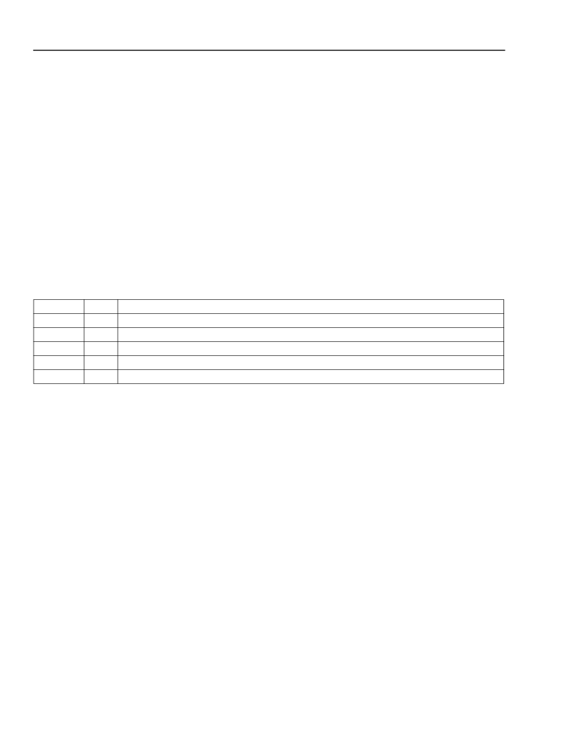
Table 2. SIO Interface Signals
Symbol
DI1
DO1
IOLD*
IOCK
SYNC
Type
I
O
I/O
I/O
I/O
Function
Serial data in 1.
Serial data out 1.
Input/output load for SIO 1.
Input/output clock for SIO 1.
Sync for SIO 1 and 2.
相關(guān)PDF資料 |
PDF描述 |
|---|---|
| T8302 | T8302 Internet Protocol Telephone Advanced RISC Machine (ARM) Ethernet QoS Using IEEE 802.1q |
| T8502 | T8502 and T8503 Dual PCM Codecs with Filters |
| T8503 | T8502 and T8503 Dual PCM Codecs with Filters |
| T8531A | T8531A/8532 Multichannel Programmable Codec Chip Set |
| T8531 | T8502 and T8503 Dual PCM Codecs with Filters |
相關(guān)代理商/技術(shù)參數(shù) |
參數(shù)描述 |
|---|---|
| T8301AX | 制造商:MOLEX 制造商全稱:Molex Electronics Ltd. 功能描述:Terminator Die |
| T8301BX | 制造商:MOLEX 制造商全稱:Molex Electronics Ltd. 功能描述:Terminator Die |
| T8301DX | 制造商:MOLEX 制造商全稱:Molex Electronics Ltd. 功能描述:Terminator Die |
| T8302 | 制造商:AGERE 制造商全稱:AGERE 功能描述:T8302 Internet Protocol Telephone Advanced RISC Machine (ARM) Ethernet QoS Using IEEE 802.1q |
| T8302A | 制造商:MOLEX 制造商全稱:Molex Electronics Ltd. 功能描述:Terminator Die |
發(fā)布緊急采購,3分鐘左右您將得到回復(fù)。