- 您現(xiàn)在的位置:買賣IC網(wǎng) > PDF目錄371179 > T8301 T8301 Internet Protocol Telephone Phone-On-A-Chip⑩ IP Solution DSP PDF資料下載
參數(shù)資料
| 型號: | T8301 |
| 英文描述: | T8301 Internet Protocol Telephone Phone-On-A-Chip⑩ IP Solution DSP |
| 中文描述: | T8301因特網(wǎng)協(xié)議電話熱線電話在一個芯片⑩DSP的IP解決方案 |
| 文件頁數(shù): | 17/190頁 |
| 文件大小: | 1535K |
| 代理商: | T8301 |
第1頁第2頁第3頁第4頁第5頁第6頁第7頁第8頁第9頁第10頁第11頁第12頁第13頁第14頁第15頁第16頁當前第17頁第18頁第19頁第20頁第21頁第22頁第23頁第24頁第25頁第26頁第27頁第28頁第29頁第30頁第31頁第32頁第33頁第34頁第35頁第36頁第37頁第38頁第39頁第40頁第41頁第42頁第43頁第44頁第45頁第46頁第47頁第48頁第49頁第50頁第51頁第52頁第53頁第54頁第55頁第56頁第57頁第58頁第59頁第60頁第61頁第62頁第63頁第64頁第65頁第66頁第67頁第68頁第69頁第70頁第71頁第72頁第73頁第74頁第75頁第76頁第77頁第78頁第79頁第80頁第81頁第82頁第83頁第84頁第85頁第86頁第87頁第88頁第89頁第90頁第91頁第92頁第93頁第94頁第95頁第96頁第97頁第98頁第99頁第100頁第101頁第102頁第103頁第104頁第105頁第106頁第107頁第108頁第109頁第110頁第111頁第112頁第113頁第114頁第115頁第116頁第117頁第118頁第119頁第120頁第121頁第122頁第123頁第124頁第125頁第126頁第127頁第128頁第129頁第130頁第131頁第132頁第133頁第134頁第135頁第136頁第137頁第138頁第139頁第140頁第141頁第142頁第143頁第144頁第145頁第146頁第147頁第148頁第149頁第150頁第151頁第152頁第153頁第154頁第155頁第156頁第157頁第158頁第159頁第160頁第161頁第162頁第163頁第164頁第165頁第166頁第167頁第168頁第169頁第170頁第171頁第172頁第173頁第174頁第175頁第176頁第177頁第178頁第179頁第180頁第181頁第182頁第183頁第184頁第185頁第186頁第187頁第188頁第189頁第190頁

Lucent Technologies Inc.
17
Advance Data Sheet
December 2000
T8301 Internet Protocol Telephone
Phone-On-A-Chip
IP Solution DSP
5 Audio Input/Output Circuitry
The discussions in this section pertain to circuitry that is outside of the dotted outline in Figure 3 on page 8.
5.1 Analog Audio Input Channels
The T8301 contains analog interfaces designed to support a 150
handset as well as an additional microphone
and two speakers.
The T8301 integrated circuit contains two audio analog inputs. There is a single-ended input (
AINAN
) to be con-
nected to a standard business telephone handset receiver. There is a differential input (
AINCP
,
AINCN
) to be con-
nected to a microphone. This provides the T8301 with the input circuitry to implement a speakerphone. The
differential input is directly connected to a 30 dB amplifier. The input select multiplexer routes
AINAN
or the output
of the fixed 30 dB amplifier to a programmable gain amplifier (PGA). The programmable gain amplifier is adjustable
from 0 dB to 21 dB in 3 dB steps. The signal output from the programmable gain amplifier is then routed to the
audio codec block to be digitized.
Each of the input signals
AINAN
,
AINCP
, and
AINCN
are ac-coupled to their T8301 inputs by a 0.2
μ
F capacitor.
The maximum signal input to the codec is 2.5 Vp-p. If the user sets the amplification to a value that would produce
a larger signal than 2.5 Vp-p, the audio codec will saturate and clip the input waveform.
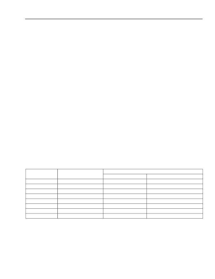
The maximum input signal from the handset or from the microphone that can be supported for each gain setting is
listed in Table 7. Since the microphone amplifier has a maximum specified signal of 40 mV, the maximum micro-
phone input is not supported for PGA settings of 0 dB and 3 dB.
5.2 Programmable Gain Amplifier (PGA)
The programmable gain amplifier is using the PGAS[2:0] bits of the
aioc_reg
(see Table 11 on page 21). The set-
table gain values and their tolerances are shown below as well as the maximum allowed input signal voltage from
each of the input signals. Inputs greater than these values will saturate the input codec and produce clipped wave-
forms.
Table 7. Programmable Gain Amplifier Maximum
Bit Code
Gain
Max Input Signal
AINAN
2.500 Vp-p
1.770 Vp-p
1.250 Vp-p
0.844 Vp-p
0.625 Vp-p
0.442 Vp-p
0.313 Vp-p
0.221 Vp-p
AINCN, AINCP
Not supported
Not supported
40.0 mVp-p
28.3 mVp-p
20.0 mVp-p
14.2 mVp-p
10.0 mVp-p
7.1 mVp-p
000
001
010
011
100
101
110
111
0 dB ± 0.5 dB
3 dB ± 0.5 dB
6 dB ± 0.5 dB
9 dB ± 0.5 dB
12 dB ± 0.5 dB
15 dB ± 1.0 dB
18 dB ± 1.0 dB
21 dB ± 1.5 dB
相關PDF資料 |
PDF描述 |
|---|---|
| T8302 | T8302 Internet Protocol Telephone Advanced RISC Machine (ARM) Ethernet QoS Using IEEE 802.1q |
| T8502 | T8502 and T8503 Dual PCM Codecs with Filters |
| T8503 | T8502 and T8503 Dual PCM Codecs with Filters |
| T8531A | T8531A/8532 Multichannel Programmable Codec Chip Set |
| T8531 | T8502 and T8503 Dual PCM Codecs with Filters |
相關代理商/技術參數(shù) |
參數(shù)描述 |
|---|---|
| T8301AX | 制造商:MOLEX 制造商全稱:Molex Electronics Ltd. 功能描述:Terminator Die |
| T8301BX | 制造商:MOLEX 制造商全稱:Molex Electronics Ltd. 功能描述:Terminator Die |
| T8301DX | 制造商:MOLEX 制造商全稱:Molex Electronics Ltd. 功能描述:Terminator Die |
| T8302 | 制造商:AGERE 制造商全稱:AGERE 功能描述:T8302 Internet Protocol Telephone Advanced RISC Machine (ARM) Ethernet QoS Using IEEE 802.1q |
| T8302A | 制造商:MOLEX 制造商全稱:Molex Electronics Ltd. 功能描述:Terminator Die |
發(fā)布緊急采購,3分鐘左右您將得到回復。