- 您現(xiàn)在的位置:買賣IC網(wǎng) > PDF目錄385942 > TNETA1561 (Texas Instruments, Inc.) ATM Segmentation and Reassembly Device with PCI Host Interface(ATM 分段和重設(shè)裝置帶SBUS主機(jī)接口) PDF資料下載
參數(shù)資料
| 型號(hào): | TNETA1561 |
| 廠商: | Texas Instruments, Inc. |
| 英文描述: | ATM Segmentation and Reassembly Device with PCI Host Interface(ATM 分段和重設(shè)裝置帶SBUS主機(jī)接口) |
| 中文描述: | 自動(dòng)柜員機(jī)分段和重組的PCI主機(jī)接口(自動(dòng)柜員機(jī)分段和重設(shè)裝置帶SBU的主機(jī)接口設(shè)備) |
| 文件頁數(shù): | 28/49頁 |
| 文件大小: | 976K |
| 代理商: | TNETA1561 |
第1頁第2頁第3頁第4頁第5頁第6頁第7頁第8頁第9頁第10頁第11頁第12頁第13頁第14頁第15頁第16頁第17頁第18頁第19頁第20頁第21頁第22頁第23頁第24頁第25頁第26頁第27頁當(dāng)前第28頁第29頁第30頁第31頁第32頁第33頁第34頁第35頁第36頁第37頁第38頁第39頁第40頁第41頁第42頁第43頁第44頁第45頁第46頁第47頁第48頁第49頁
TNETA1561
ATM SEGMENTATION AND REASSEMBLY DEVICE
WITH PCI HOST INTERFACE
SDNS028B – OCTOBER 1994 – REVISED JANUARY 1996
28
POST OFFICE BOX 655303
DALLAS, TEXAS 75265
PRINCIPLES OF OPERATION
transmit descriptor rings and DMA (continued)
Each descriptor-ring entry contains a control bit that indicates whether a buffer is queued up for transmission.
The DMA entry for each BWG contains a pointer to the first item in the queue in the corresponding descriptor
ring. An idle cell is transmitted if the control bit in the descriptor entry indicates an inactive entry. The DMA entry
has a bit that allows the host to disable any BWG.
receive free-buffer rings and DMA
The PCI SAR uses buffer pointers from two free-buffer rings to place the incoming packet data in the host
memory. These are called small free-buffer ring and big free-buffer ring. Each receive BWG has a control bit
indicating the type of buffer it uses: small or big. These buffers are preallocated by the host application for the
next packet and not by the BWG.
The PCI SAR supports 1023 receive DMA channels and 1023 VCIs. The incoming VCI indexes the receive DMA
channels. BWG 0 is reserved to process information for OAM cells.
completion rings
The PCI SAR indicates completion of packet processing in either direction to the host via an interrupt and by
posting entries to receive and transmit completion rings. Each completion ring accepts up to 256 entries. A
control bit in each entry of the completion ring prevents the PCI SAR from overwriting an entry that has not been
processed by the host.
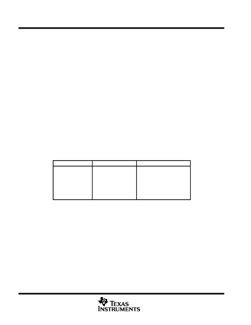
data structure
The PCI SAR data structure and contents of various physical locations are summarized below:
CONTROL MEMORY
HOST MEMORY
INTERNAL REGISTERS
BWG table
TX descriptor rings (255)
PCI SAR operational registers
TX DMA states
TX completion ring
PCI SAR configuration registers
RX DMA states
Small free-buffer ring
PCI configuration space
Initialization block
Big free-buffer ring
RX completion ring
Data buffers
The parameters necessary for booting the device are stored in the PCI configuration space. Some systems may
use an external EPROM that contains the booting sequence.
The system has a bus width of four bytes and all transactions are conducted on 4-byte boundaries. The PCI
SAR uses little-endian addressing as a PCI-bus device. Each descriptor ring has 256 entries and each
descriptor-ring entry consists of four words. Each descriptor ring is aligned to a 4K-byte boundary in host
memory with each entry aligned to a 16-byte boundary.
The PCI SAR has two receive free-buffer rings, one transmit completion ring, and one receive completion ring.
The current pointer to each of these rings is stored in the initialization block in the control memory. An entry in
each transmit DMA channel points to one of the 255 transmit descriptor rings in host memory.
Each DMA-channel entry consists of eight words and is located in control memory. The DMA entries on both
transmit and receive have an OWN bit that is set when the DMA channel is active. The descriptor-ring entries,
the completion-ring entries, and the free-buffer ring entries have an OWN bit that is set when the entry belongs
to the PCI SAR.
相關(guān)PDF資料 |
PDF描述 |
|---|---|
| TNETA1600 | SONET/SDH ATM Receiver/Transmitter for 622.08-Mit/s or 155.52-Mbit/s Operation(SONET/SDH ATM接收器/傳送器) |
| TNETA1610 | STS-12c/STM-4 Receiver/Transmitter with Clock Recovery/Generation(STS-12C/STM-4接收/傳送器) |
| TNETA1611 | STS-12c/STM-4 Receiver/Transimitter(STS-12C/STM-4接收/傳送器) |
| TNETA1630 | 622.08-MHz Clock-Recovery Device(622.08-MHz時(shí)鐘發(fā)生裝置) |
| TO-252 | TO-252 (MP-3Z) |
相關(guān)代理商/技術(shù)參數(shù) |
參數(shù)描述 |
|---|---|
| TNETA1561PGC | 制造商:Rochester Electronics LLC 功能描述:- Bulk |
| TNETA1570 | 制造商:TI 制造商全稱:Texas Instruments 功能描述:ATM SEGMENTATION AND REASSEMBLY DEVICE WITH INTEGRATED 64-BIT PCI-HOST INTERFACE |
| TNETA1570MFP | 制造商:未知廠家 制造商全稱:未知廠家 功能描述:ATM/SONET Segmentation and Reassembly Circuit |
| TNETA1570PGW | 制造商:Rochester Electronics LLC 功能描述:- Bulk |
| TNETA1575 | 制造商:TI 制造商全稱:Texas Instruments 功能描述:ATM SEGMENTATION AND REASSEMBLY DEVICE WITH PCI-HOST AND COPROCESSOR INTERFACES |
發(fā)布緊急采購,3分鐘左右您將得到回復(fù)。