- 您現(xiàn)在的位置:買賣IC網(wǎng) > PDF目錄366550 > AM79C974 (Advanced Micro Devices, Inc.) PCnetTM-SCSI Combination Ethernet and SCSI Controller for PCI Systems PDF資料下載
參數(shù)資料
| 型號(hào): | AM79C974 |
| 廠商: | Advanced Micro Devices, Inc. |
| 英文描述: | PCnetTM-SCSI Combination Ethernet and SCSI Controller for PCI Systems |
| 中文描述: | PCnetTM -的SCSI結(jié)合以太網(wǎng)和SCSI控制器PCI系統(tǒng) |
| 文件頁(yè)數(shù): | 64/153頁(yè) |
| 文件大小: | 838K |
| 代理商: | AM79C974 |
第1頁(yè)第2頁(yè)第3頁(yè)第4頁(yè)第5頁(yè)第6頁(yè)第7頁(yè)第8頁(yè)第9頁(yè)第10頁(yè)第11頁(yè)第12頁(yè)第13頁(yè)第14頁(yè)第15頁(yè)第16頁(yè)第17頁(yè)第18頁(yè)第19頁(yè)第20頁(yè)第21頁(yè)第22頁(yè)第23頁(yè)第24頁(yè)第25頁(yè)第26頁(yè)第27頁(yè)第28頁(yè)第29頁(yè)第30頁(yè)第31頁(yè)第32頁(yè)第33頁(yè)第34頁(yè)第35頁(yè)第36頁(yè)第37頁(yè)第38頁(yè)第39頁(yè)第40頁(yè)第41頁(yè)第42頁(yè)第43頁(yè)第44頁(yè)第45頁(yè)第46頁(yè)第47頁(yè)第48頁(yè)第49頁(yè)第50頁(yè)第51頁(yè)第52頁(yè)第53頁(yè)第54頁(yè)第55頁(yè)第56頁(yè)第57頁(yè)第58頁(yè)第59頁(yè)第60頁(yè)第61頁(yè)第62頁(yè)第63頁(yè)當(dāng)前第64頁(yè)第65頁(yè)第66頁(yè)第67頁(yè)第68頁(yè)第69頁(yè)第70頁(yè)第71頁(yè)第72頁(yè)第73頁(yè)第74頁(yè)第75頁(yè)第76頁(yè)第77頁(yè)第78頁(yè)第79頁(yè)第80頁(yè)第81頁(yè)第82頁(yè)第83頁(yè)第84頁(yè)第85頁(yè)第86頁(yè)第87頁(yè)第88頁(yè)第89頁(yè)第90頁(yè)第91頁(yè)第92頁(yè)第93頁(yè)第94頁(yè)第95頁(yè)第96頁(yè)第97頁(yè)第98頁(yè)第99頁(yè)第100頁(yè)第101頁(yè)第102頁(yè)第103頁(yè)第104頁(yè)第105頁(yè)第106頁(yè)第107頁(yè)第108頁(yè)第109頁(yè)第110頁(yè)第111頁(yè)第112頁(yè)第113頁(yè)第114頁(yè)第115頁(yè)第116頁(yè)第117頁(yè)第118頁(yè)第119頁(yè)第120頁(yè)第121頁(yè)第122頁(yè)第123頁(yè)第124頁(yè)第125頁(yè)第126頁(yè)第127頁(yè)第128頁(yè)第129頁(yè)第130頁(yè)第131頁(yè)第132頁(yè)第133頁(yè)第134頁(yè)第135頁(yè)第136頁(yè)第137頁(yè)第138頁(yè)第139頁(yè)第140頁(yè)第141頁(yè)第142頁(yè)第143頁(yè)第144頁(yè)第145頁(yè)第146頁(yè)第147頁(yè)第148頁(yè)第149頁(yè)第150頁(yè)第151頁(yè)第152頁(yè)第153頁(yè)

AMD
P R E L I M I N A R Y
64
Am79C974
Hardware Access
PCnet-SCSI Controller Master Accesses
The Am79C974 controller has a bus interface compat-
ible with PCI specification revision 2.0.
Complete descriptions of the signals involved in bus
master transactions for each mode may be found in the
pin description section of this document. Timing dia-
grams for master accesses may be found in the block
description section for the Bus Interface Unit. This sec-
tion simply lists the types of master accesses that will be
performed by the Am79C974 controller with respect to
data size and address information.
The Am79C974 controller will support master accesses
only to 32-bit peripherals. The Am79C974 controller
does not support master accesses to 8-bit or 16-bit
memory. The Am79C974 controller is not compatible
with 8-bit systems, since there is no mode that supports
Am79C974 controller accesses to 8-bit peripherals.
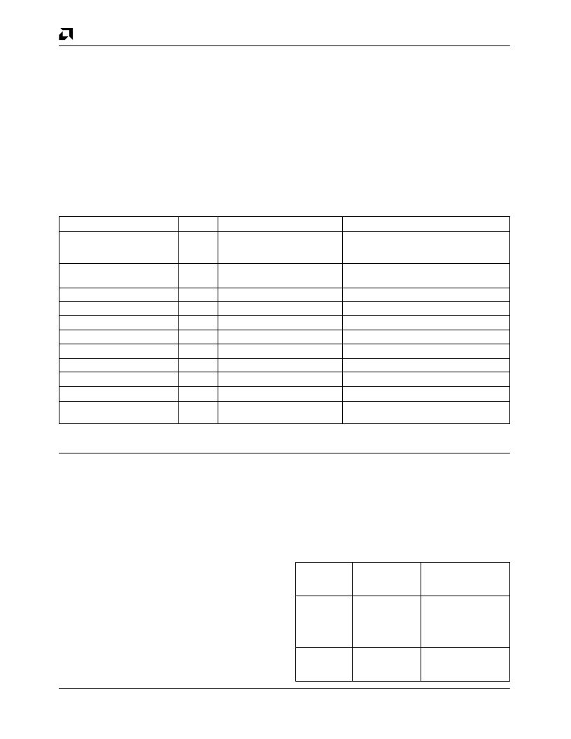
Table 3 describes all possible bus master accesses that
the Am79C974 controller will perform. The right most
column lists all operations that may execute the given
access:
Table 3. Bus Master Accesses
Access
Mode
BE
[3:0]
Operation
4-byte read
Read
0000
descriptor read
or initialization block read
or transmit data buffer read
4-byte write
Write
0000
descriptor write
or receive data buffer write
3-byte write
Write
1000
receive data buffer write
3-byte write
Write
0001
receive data buffer write
2-byte write
Write
1100
receive data buffer write
2-byte write
Write
1001*
receive data buffer write
2-byte write
Write
0011
receive data buffer write
1-byte write
Write
1110
receive data buffer write
1-byte write
Write
1101*
receive data buffer write
1-byte write
Write
1011*
receive data buffer write
1-byte write
Write
0111
descriptor write
or receive data buffer write
* Cases marked with an asterisk represent extreme boundary conditions that are the result of programming one- and two-byte
buffer sizes, and therefore will not be seen under normal circumstances.
Note that all Am79C974 controller master read opera-
tions will always activate all byte enables. Therefore, no
one-, two- or three-byte read operations are indicated in
the table.
In the instance where a transmit buffer pointer address
begins on a non-DWORD boundary, the pointer will be
truncated to the next DWORD boundary address that
lies below the given pointer address and the first read
access from the transmit buffer will be indicated on the
byte enable signals as a four-byte read from this ad-
dress. Any data from byte lanes that lie outside of the
boundary indicated by the buffer pointer will be dis-
carded inside of the Am79C974 controller. Similarly, if
the end of a transmit buffer occurs on a non-DWORD
boundary, then all byte lanes will be indicated as active
by the byte enable signals, and any data from byte lanes
that lie outside of the boundary indicated by the buffer
pointer will be discarded inside of the Am79C974
controller.
Slave Access to I/O Resources
The Am79C974 device is always a 32-bit peripheral on
the system bus. However, the width of individual soft-
ware resources on board the Am79C974 controller may
be either 16-bits or 32-bits. The Am79C974 controller
I/O resource widths are determined by the setting of the
DWIO bit as indicated in the following table:
Am79C974
Controller I/O
DWIO Setting Resource Width Example Application
DWIO = 0
16-bit
Existing PCnet-ISA
driver that assumes
16-bit I/O mapping
and 16-bit resource
widths
DWIO = 1
32-bit
New drivers written
specifically for the
Am79C974 controller
相關(guān)PDF資料 |
PDF描述 |
|---|---|
| AM79C974KCW | PCnetTM-SCSI Combination Ethernet and SCSI Controller for PCI Systems |
| AM79C975 | PCnet⑩-FAST III Single-Chip 10/100 Mbps PCI Ethernet Controller with Integrated PHY |
| AM79C973 | PCnet⑩-FAST III Single-Chip 10/100 Mbps PCI Ethernet Controller with Integrated PHY |
| AM79C973KCW | PCnet⑩-FAST III Single-Chip 10/100 Mbps PCI Ethernet Controller with Integrated PHY |
| AM79C975KCW | PCnet⑩-FAST III Single-Chip 10/100 Mbps PCI Ethernet Controller with Integrated PHY |
相關(guān)代理商/技術(shù)參數(shù) |
參數(shù)描述 |
|---|---|
| AM79C974KC | 制造商:Advanced Micro Devices 功能描述: |
| AM79C974KC/W | 制造商:未知廠家 制造商全稱:未知廠家 功能描述:LAN Node Controller |
| AM79C974KCW | 制造商:AMD 制造商全稱:Advanced Micro Devices 功能描述:PCnetTM-SCSI Combination Ethernet and SCSI Controller for PCI Systems |
| AM79C975 | 制造商:AMD 制造商全稱:Advanced Micro Devices 功能描述:PCnet⑩-FAST III Single-Chip 10/100 Mbps PCI Ethernet Controller with Integrated PHY |
發(fā)布緊急采購(gòu),3分鐘左右您將得到回復(fù)。