- 您現(xiàn)在的位置:買賣IC網(wǎng) > PDF目錄370702 > HSP3824VI (Harris Corporation) Direct Sequence Spread Spectrum Baseband Processor PDF資料下載
參數(shù)資料
| 型號(hào): | HSP3824VI |
| 廠商: | Harris Corporation |
| 元件分類: | 基帶處理器 |
| 英文描述: | Direct Sequence Spread Spectrum Baseband Processor |
| 中文描述: | 直接序列擴(kuò)頻基帶處理器 |
| 文件頁數(shù): | 39/41頁 |
| 文件大小: | 276K |
| 代理商: | HSP3824VI |
第1頁第2頁第3頁第4頁第5頁第6頁第7頁第8頁第9頁第10頁第11頁第12頁第13頁第14頁第15頁第16頁第17頁第18頁第19頁第20頁第21頁第22頁第23頁第24頁第25頁第26頁第27頁第28頁第29頁第30頁第31頁第32頁第33頁第34頁第35頁第36頁第37頁第38頁當(dāng)前第39頁第40頁第41頁

39
Specifications HSP3824 at 44MHz
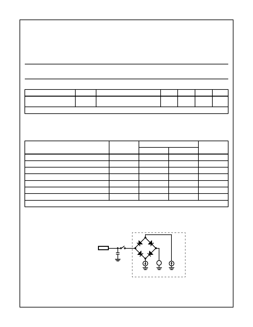
Test Circuit
NOTES:
1. Includes Stray and JIG Capacitance
2. Switch S1 Open for I
CCSB
and I
CCOP
FIGURE 22. TEST LOAD CIRCUIT
Absolute Maximum Ratings
Supply Voltage . . . . . . . . . . . . . . . . . . . . . . . . . . . . . . . . . . . . . .7.0V
Input, Output or I/O Voltage . . . . . . . . . . . .GND -0.5V to V
CC
+0.5V
Storage Temperature Range . . . . . . . . . . . . . . . . . -65
o
C to +150
o
C
Junction Temperature. . . . . . . . . . . . . . . . . . . . . . . . . . . . . . . 150
o
C
Lead Temperature (Soldering 10s) (Lead Tips Only) . . . . . . +300
o
C
ESD Classification . . . . . . . . . . . . . . . . . . . . . . . . . . . . . . . . Class 1
Reliability Information
Thermal Resistance (Typical)
TQFP Package . . . . . . . . . . . . . . . . . . . . . . . . . . . .
Package Power Dissipation at 85
o
C
TQFP Package . . . . . . . . . . . . . . . . . . . . . . . . . . . . . . . . . . 0.81W
Gate Count . . . . . . . . . . . . . . . . . . . . . . . . . . . . . . . . . 25,000 Gates
θ
JA
80
o
C/W
CAUTION: Stresses above those listed in “Absolute Maximum Ratings” may cause permanent damage to the device. This is a stress only rating and operation
of the device at these or any other conditions above those indicated in the operational sections of this specification is not implied.
Operating Conditions
Operating Voltage Range . . . . . . . . . . . . . . . . . . . . . +3.3V to +5.0V
Operating Temperature Range . . . . . . . . . . . . . . . . .-40
o
C to +85
o
C
DC Electrical Specifications
V
CC
= 3.3V to 5.0V T
A
= -40
o
to +85
o
C
PARAMETER
SYMBOL
TEST CONDITIONS
MIN
TYP
MAX
UNITS
Power Supply Current
I
CCOP
V
CC
= Max, CLK Frequency 44MHz
(Notes 1, 2)
-
105
111
mA
See previous DC table for remaining DC specifications
NOTES:
4. Output load 30pF, I
CCOP
= 5.5 + 4.7(V) + 3.7E - 7 (V)(f); V = Volts, f = Freq. Example: 5.5 + 4.7(5.0) + 3.7E - 7(5.0)(44E6) = 111
5. Not tested, but characterized at initial design and major process/design changes.
AC Electrical Specifications
V
CC
= 3.3V to 5.0V, T
A
= -40
o
to +85
o
, (Note 1)
PARAMETER
SYMBOL
44MHz
UNITS
MIN
MAX
CLK Period (MCLK)
t
CP
22.5
-
ns
CLK High (MCLK)
t
CH
9
-
ns
CLK Low (MCLK)
t
CL
9
-
ns
TXCLK, TXRDY, I, Q from MCLK
t
D2
-
25
ns
RXCLK, MD_RDY, RXD from MCLK
t
D3
-
25
ns
TEST 0-7, CCA, AGC, from MCLK
t
D4
-
27
ns
ANSTEL, TEST_CK
-
-
-
-
See previous AC table for remaining AC specifications
NOTES:
1. AC tests performed with C
L
= 40pF, I
OL
= 2mA, and I
OH
= -1mA. Input reference level all inputs 1.5V. Test V
IH
= Vcc, V
IL
= 0V; V
OH
= V
OL
= V
CC
/2.
EQUIVALENT CIRCUIT
C
L
IOH
1.5V
IOL
DUT
S
1
±
(NOTE 2)
(NOTE 1)
相關(guān)PDF資料 |
PDF描述 |
|---|---|
| HSR101 | Silicon Schottky Barrier Diode for Various detector, High speed switching(用于多種檢波和高速開關(guān)的肖特基勢(shì)壘二極管) |
| HSRD1056RH165S | Converter IC |
| HSRD1056RH169H | Converter IC |
| HSRD1056RH169S | Converter IC |
| HSRD1056RH240H | Converter IC |
相關(guān)代理商/技術(shù)參數(shù) |
參數(shù)描述 |
|---|---|
| HSP3824VI96S5001 | 制造商:Harris Corporation 功能描述: |
| HSP40223221 | 制造商:PARMAR 功能描述:BALLAST HPS/MH 400W 制造商:PARMAR 功能描述:BALLAST, HPS/MH, 400W |
| HSP4070C | 制造商:JLWORLD 制造商全稱:JLWORLD 功能描述:SPEAKER SOUND GENERATORS |
| HSP40G-8 | 制造商:JLWORLD 制造商全稱:JLWORLD 功能描述:SPEAKER SOUND GENERATORS |
| HSP43124 | 制造商:INTERSIL 制造商全稱:Intersil Corporation 功能描述:Serial I/O Filter |
發(fā)布緊急采購,3分鐘左右您將得到回復(fù)。