- 您現(xiàn)在的位置:買賣IC網 > PDF目錄360744 > ICS1892 10Base-T/100Base-TX Integrated PHYceiver PDF資料下載
參數(shù)資料
| 型號: | ICS1892 |
| 英文描述: | 10Base-T/100Base-TX Integrated PHYceiver |
| 文件頁數(shù): | 75/148頁 |
| 文件大小: | 816K |
| 代理商: | ICS1892 |
第1頁第2頁第3頁第4頁第5頁第6頁第7頁第8頁第9頁第10頁第11頁第12頁第13頁第14頁第15頁第16頁第17頁第18頁第19頁第20頁第21頁第22頁第23頁第24頁第25頁第26頁第27頁第28頁第29頁第30頁第31頁第32頁第33頁第34頁第35頁第36頁第37頁第38頁第39頁第40頁第41頁第42頁第43頁第44頁第45頁第46頁第47頁第48頁第49頁第50頁第51頁第52頁第53頁第54頁第55頁第56頁第57頁第58頁第59頁第60頁第61頁第62頁第63頁第64頁第65頁第66頁第67頁第68頁第69頁第70頁第71頁第72頁第73頁第74頁當前第75頁第76頁第77頁第78頁第79頁第80頁第81頁第82頁第83頁第84頁第85頁第86頁第87頁第88頁第89頁第90頁第91頁第92頁第93頁第94頁第95頁第96頁第97頁第98頁第99頁第100頁第101頁第102頁第103頁第104頁第105頁第106頁第107頁第108頁第109頁第110頁第111頁第112頁第113頁第114頁第115頁第116頁第117頁第118頁第119頁第120頁第121頁第122頁第123頁第124頁第125頁第126頁第127頁第128頁第129頁第130頁第131頁第132頁第133頁第134頁第135頁第136頁第137頁第138頁第139頁第140頁第141頁第142頁第143頁第144頁第145頁第146頁第147頁第148頁
Chapter 8
Management Register Set
ICS1892, Rev. D, 2/26/01
February 26, 2001
75
ICS1892
2000-2001, Integrated Circuit Systems, Inc.
All rights reserved.
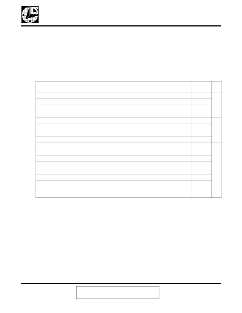
8.6
Register 4: Auto-Negotiation Register
Table 8-11
lists the bits for the Auto-Negotiation Register. An STA uses this register to select the ICS1892
capabilities that it wants to advertise to its remote link partner. During the auto-negotiation process, the
ICS1892 advertises (that is, exchanges) capability data with its remote link partner by using a pre-defined
Link Code Word. The Link Code Word is embedded in the Fast Link Pulses exchanged between PHYs,
when the ICS1892 has its Auto-Negotiation sublayer enabled. The value of the Link Control Word is
established based on the value of the bits in this register.
Note:
For an explanation of acronyms used in
Table 8-5
, see
Chapter 1, “Abbreviations and Acronyms”
.
As per the IEEE Std 802.3u, during any write operation to any bit in this register, the STA must write the default value
to all Reserved bits.
Note 1:
In Hardware mode (that is, HW/SW pin is logic zero), this bit is a Read-Only bit.
In Software mode (that is, HW/SW pin is logic one), this bit is a Command Override Write bit.
8.6.1
Next Page (bit 4.15)
This bit indicates whether the ICS1892 uses the Next Page Mode functions during the auto-negotiation
process. If bit 4.15 is logic:
Zero, then the ICS1892 indicates to its remote link partner that these features are disabled. (Although
the default value of this bit is logic zero, the ICS1892 does support the Next Page function.)
One, then the ICS1892 advertises to its remote link partner that this feature is enabled.
Table 8-11.
Auto-Negotiation Advertisement Register (register 4 [0x04])
Bit
Definition
When Bit = 0
When Bit = 1
Ac-
cess
SF
De-
fault
Hex
4.15
Next Page
Next page not supported
Next page supported
R/W
–
0
0
4.14
IEEE reserved
Always 0
N/A
CW
–
0
4.13
Remote fault
Locally, no faults detected
Local fault detected
R/W
–
0
4.12
IEEE reserved
Always 0
N/A
CW
–
0
4.11
IEEE reserved
Always 0
N/A
CW
–
0
1
4.10
IEEE reserved
Always 0
N/A
CW
–
0
4.9
100Base-T4
Always 0. (Not supported.)
N/A
CW
–
0
4.8
100Base-TX, full duplex
Do not advertise ability
Advertise ability
Note 1
–
1
4.7
100Base-TX, half duplex Do not advertise ability
Advertise ability
Note 1
–
1
E
4.6
10Base-T, full duplex
Do not advertise ability
Advertise ability
Note 1
–
1
4.5
10Base-T half duplex
Do not advertise ability
Advertise ability
Note 1
–
1
4.4
Selector Field bit S4
IEEE 802.3-specified default N/A
CW
–
0
4.3
Selector Field bit S3
IEEE 802.3-specified default N/A
CW
–
0
1
4.2
Selector Field bit S2
IEEE 802.3-specified default N/A
CW
–
0
4.1
Selector Field bit S1
IEEE 802.3-specified default N/A
CW
–
0
4.0
Selector Field bit S0
N/A
IEEE 802.3-specified
default
CW
–
1
相關PDF資料 |
PDF描述 |
|---|---|
| ICS1892Y | 10Base-T/100Base-TX Integrated PHYceiver |
| ICS1892Y-10 | 10Base-T/100Base-TX Integrated PHYceiver |
| ICS1892Y-14 | 10Base-T/100Base-TX Integrated PHYceiver |
| ICS1893AF | 3.3V 10Base-T/100Base-TX Integrated PHYceiverTM |
| ICS1893Y-10 | 3.3V 10Base-T/100Base-TX Integrated PHYceiverTM |
相關代理商/技術參數(shù) |
參數(shù)描述 |
|---|---|
| ICS1892Y | 制造商:ICS 制造商全稱:ICS 功能描述:10Base-T/100Base-TX Integrated PHYceiver |
| ICS1892Y-10 | 制造商:ICS 制造商全稱:ICS 功能描述:10Base-T/100Base-TX Integrated PHYceiver |
| ICS1892Y-14 | 制造商:ICS 制造商全稱:ICS 功能描述:10Base-T/100Base-TX Integrated PHYceiver |
| ICS1893 | 制造商:ICS 制造商全稱:ICS 功能描述:3.3-V 10Base-T/100Base-TX Integrated PHYceiver |
| ICS1893_09 | 制造商:ICS 制造商全稱:ICS 功能描述:3.3-V 10Base-T/100Base-TX Integrated PHYceiver? |
發(fā)布緊急采購,3分鐘左右您將得到回復。