- 您現(xiàn)在的位置:買賣IC網 > PDF目錄367625 > MFRC53001T (NXP Semiconductors N.V.) ISO-IEC 14443 A Reader IC PDF資料下載
參數(shù)資料
| 型號: | MFRC53001T |
| 廠商: | NXP Semiconductors N.V. |
| 元件分類: | 通信及網絡 |
| 英文描述: | ISO-IEC 14443 A Reader IC |
| 封裝: | MFRC53001T/0FE<SOT287-1 (SO32)|<<http://www.nxp.com/packages/SOT287-1.html<1<week 5, 2005,;MFRC53001T/0FE<SOT287-1 (SO32)|<<http://www.nxp.com/packages/SOT287-1.html<1 |
| 文件頁數(shù): | 31/115頁 |
| 文件大小: | 2590K |
| 代理商: | MFRC53001T |
第1頁第2頁第3頁第4頁第5頁第6頁第7頁第8頁第9頁第10頁第11頁第12頁第13頁第14頁第15頁第16頁第17頁第18頁第19頁第20頁第21頁第22頁第23頁第24頁第25頁第26頁第27頁第28頁第29頁第30頁當前第31頁第32頁第33頁第34頁第35頁第36頁第37頁第38頁第39頁第40頁第41頁第42頁第43頁第44頁第45頁第46頁第47頁第48頁第49頁第50頁第51頁第52頁第53頁第54頁第55頁第56頁第57頁第58頁第59頁第60頁第61頁第62頁第63頁第64頁第65頁第66頁第67頁第68頁第69頁第70頁第71頁第72頁第73頁第74頁第75頁第76頁第77頁第78頁第79頁第80頁第81頁第82頁第83頁第84頁第85頁第86頁第87頁第88頁第89頁第90頁第91頁第92頁第93頁第94頁第95頁第96頁第97頁第98頁第99頁第100頁第101頁第102頁第103頁第104頁第105頁第106頁第107頁第108頁第109頁第110頁第111頁第112頁第113頁第114頁第115頁

MFRC530_33
All information provided in this document is subject to legal disclaimers.
NXP B.V. 2010. All rights reserved.
Product data sheet
PUBLIC
Rev. 3.3 — 6 July 2010
057433
31 of 115
NXP Semiconductors
MFRC530
ISO/IEC 14443 A Reader IC
9.10 Receiver circuit
The MFRC530 uses an integrated quadrature demodulation circuit enabling it to extract
the ISO/IEC 14443 A compliant subcarrier from the 13.56 MHz ASK modulated signal
applied to pin RX.
The quadrature demodulator uses two different clocks (Q-clock and I-clock) with a
phase-shift of 90
°
between them. Both resulting subcarrier signals are amplified, filtered
and forwarded to the correlation circuitry. The correlation results are evaluated, digitized
and then passed to the digital circuitry. Various adjustments can be made to obtain
optimum performance for all processing units.
9.10.1
Receiver circuit block diagram
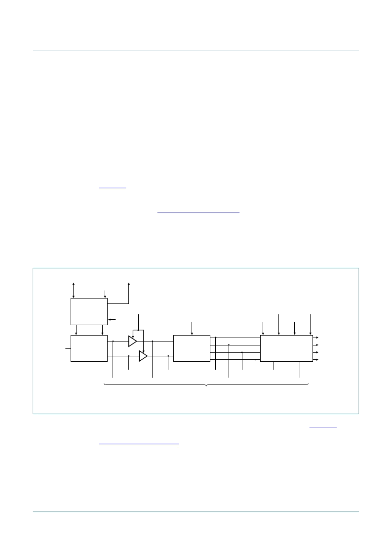
Figure 11
shows the block diagram of the receiver circuit. The receiving process can be
broken down in to several steps. Quadrature demodulation of the 13.56 MHz carrier signal
is performed. To achieve the optimum performance, automatic Q-clock calibration is
recommended (see
Section 9.10.2.1 on page 32
).
The demodulated signal is amplified by an adjustable amplifier. A correlation circuit
calculates the degree of similarity between the expected and the received signal. The
BitPhase register enables correlation interval position alignment with the received signal’s
bit grid. In the evaluation and digitizer circuitry, the valid bits are detected and the digital
results are sent to the FIFO buffer. Several tuning steps are possible for this circuit.
The signal can be observed on its way through the receiver as shown in
Figure 11
. One
signal at a time can be routed to pin AUX using the TestAnaSelect register as described in
Section 15.2.2 on page 101
.
9.10.2
Receiver operation
In general, the default settings programmed in the StartUp initialization file are suitable for
use with the MFRC530 to MIFARE card data communication. However, in some
environments specific user settings will achieve better performance.
Fig 11. Receiver circuit block diagram
001aak615
ClkQDelay[4:0]
ClkQCalib
ClkQ180Deg
BitPhase[7:0]
CORRELATION
CIRCUITRY
EVALUATION
AND
DIGITIZER
CIRCUITRY
MinLevel[3:0]
CollLevel[3:0]
RxWait[7:0]
RcvClkSell
s_valid
s_data
s_coll
s_clock
Gain[1:0]
to
TestAnaOutSel
clock
I TO Q
CONVERSION
I-clock
Q-clock
13.56 MHz
DEMODULATOR
RX
VCorrDI
VCorrNI
VCorrDQ
VCorrNQ
VEvalR
VEvalL
VRxFollQ
VRxFollI
VRxAmpI
VRxAmpQ
相關PDF資料 |
PDF描述 |
|---|---|
| MFRC53101T | ISO-IEC 14443 reader IC |
| MFRX85201HD | Secure contactless reader solution |
| MMBD4148 | High-speed switching diode |
| MMBD6050-V-GS08 | SWITING 70V 0.2A 3PIN SOT-23 - Tape and Reel |
| MMBD6050-V-GS18 | SWITING 70V 0.2A 3PIN SOT-23 - Tape and Reel |
相關代理商/技術參數(shù) |
參數(shù)描述 |
|---|---|
| MFRC53001T/0FE | 制造商:PHILIPS 制造商全稱:NXP Semiconductors 功能描述:ISO/IEC 14443 A Reader IC |
| MFRC53001T/0FE,112 | 功能描述:RFID應答器 MIFARE HS READER RoHS:否 制造商:Murata 存儲容量:512 bit 工作溫度范圍:- 40 C to + 85 C 安裝風格:SMD/SMT 封裝 / 箱體: 封裝:Reel |
| MFRC53001T/0FE,518 | 功能描述:RFID應答器 IC READER 13.56MHZ RoHS:否 制造商:Murata 存儲容量:512 bit 工作溫度范圍:- 40 C to + 85 C 安裝風格:SMD/SMT 封裝 / 箱體: 封裝:Reel |
| MFRC53001T/0FE112 | 制造商:NXP Semiconductors 功能描述:CNTCLESS RC 3.3V ISO14443-A/B |
| MFRC531 | 制造商:PHILIPS 制造商全稱:NXP Semiconductors 功能描述:Short Form Specification |
發(fā)布緊急采購,3分鐘左右您將得到回復。