- 您現(xiàn)在的位置:買賣IC網(wǎng) > PDF目錄373631 > TFRA08C13 (Lineage Power) Ultraframer DS3/E3/DS2/E2/DS1/E1/DS0 PDF資料下載
參數(shù)資料
| 型號: | TFRA08C13 |
| 廠商: | Lineage Power |
| 元件分類: | 通信及網(wǎng)絡(luò) |
| 英文描述: | Ultraframer DS3/E3/DS2/E2/DS1/E1/DS0 |
| 中文描述: | Ultraframer DS3/E3/DS2/E2/DS1/E1/DS0 |
| 文件頁數(shù): | 78/188頁 |
| 文件大小: | 3047K |
| 代理商: | TFRA08C13 |
第1頁第2頁第3頁第4頁第5頁第6頁第7頁第8頁第9頁第10頁第11頁第12頁第13頁第14頁第15頁第16頁第17頁第18頁第19頁第20頁第21頁第22頁第23頁第24頁第25頁第26頁第27頁第28頁第29頁第30頁第31頁第32頁第33頁第34頁第35頁第36頁第37頁第38頁第39頁第40頁第41頁第42頁第43頁第44頁第45頁第46頁第47頁第48頁第49頁第50頁第51頁第52頁第53頁第54頁第55頁第56頁第57頁第58頁第59頁第60頁第61頁第62頁第63頁第64頁第65頁第66頁第67頁第68頁第69頁第70頁第71頁第72頁第73頁第74頁第75頁第76頁第77頁當(dāng)前第78頁第79頁第80頁第81頁第82頁第83頁第84頁第85頁第86頁第87頁第88頁第89頁第90頁第91頁第92頁第93頁第94頁第95頁第96頁第97頁第98頁第99頁第100頁第101頁第102頁第103頁第104頁第105頁第106頁第107頁第108頁第109頁第110頁第111頁第112頁第113頁第114頁第115頁第116頁第117頁第118頁第119頁第120頁第121頁第122頁第123頁第124頁第125頁第126頁第127頁第128頁第129頁第130頁第131頁第132頁第133頁第134頁第135頁第136頁第137頁第138頁第139頁第140頁第141頁第142頁第143頁第144頁第145頁第146頁第147頁第148頁第149頁第150頁第151頁第152頁第153頁第154頁第155頁第156頁第157頁第158頁第159頁第160頁第161頁第162頁第163頁第164頁第165頁第166頁第167頁第168頁第169頁第170頁第171頁第172頁第173頁第174頁第175頁第176頁第177頁第178頁第179頁第180頁第181頁第182頁第183頁第184頁第185頁第186頁第187頁第188頁
Preliminary Data Sheet
October 2000
TFRA08C13 OCTAL T1/E1 Framer
78
L Lucent Technologies Inc.
Alarms and Performance Monitoring
(continued)
Line Test Patterns
Test patterns may be transmitted to the line through either register FRM_PR20 or register FRM_PR69. Only one of
these sources may be active at the same time. Signaling must be inhibited while sending these test patterns.
Transmit Line Test Patterns—Using Register FRM_PR20
The transmit framer can be programmed through register FRM_PR20 to transmit various test patterns. These test
patterns, when enabled, overwrite the received CHI data. The test patterns available using register FRM_PR20
are:
I
The unframed-AIS pattern which consists of a continuous bit stream of ones (. . . 111111 . . .) enabled by setting
register FRM_PR20 bit 0 to 1.
I
The unframed-auxiliary pattern which consists of a continuous bit stream of alternating ones and 0s (. . .
10101010 . . .) enabled by setting register FRM_PR20 bit 1 to 1.
I
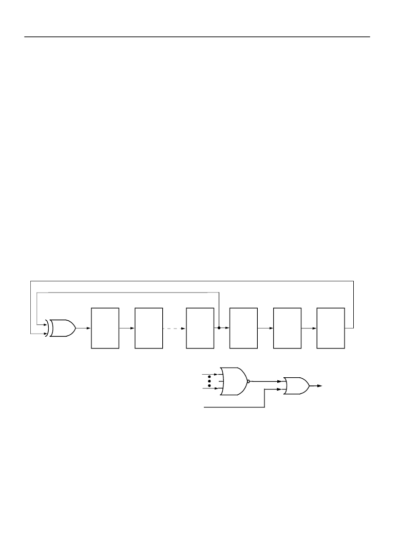
The quasi-random test signal, enabled by setting register FRM_PR20 bit 3 to 1, which consists of the following:
— A pattern produced by means of a 20-stage shift register with feedback taken from the seventeenth and twen-
tieth stages via an exclusive-OR gate to the first stage. The output is taken from the twentieth stage and is
forced to a 1 state whenever the next 14 stages (19 through 6) are all 0. The pattern length is
1,048,575 or 2
20
– 1 bits. This pattern is described in detail in AT&T Technical Reference 62411 [5] Appendix
and illustrated in Figure 29.
— Valid framing bits.
— Valid transmit facility data link (TFDL) bit information.
— Valid CRC bits.
5-3915(F).dr.1
Figure 29. 20-Stage Shift Register Used to Generate the Quasi-Random Signal
I
The pseudorandom test pattern, enabled by setting register FRM_PR20 bit 2 to 1, which consists of:
— A 2
15
– 1 pattern inserted in the entire payload (time slots 1—24 in DS1 and time slots 1—32 in CEPT), as
described by ITU Rec. 0.151 and illustrated in Figure 30.
— Valid framing pattern.
— Valid transmit facility data link (TFDL) bit data.
— Valid CRC bits.
D
D-TYPE FLIP-FLOPS
#1
D
D
#2
#17
D
#18
D
D
#19
#20
A
B
C
XOR
#6
#19
NOR
#20
QUASI-RANDOM TEST OUTPUT
OR
相關(guān)PDF資料 |
PDF描述 |
|---|---|
| TFS380C | VI TELEFILTER Filter specification |
| TFT0675F | Anti-Aliasing and Reconstruction TFT range |
| TFT0675S | Anti-Aliasing and Reconstruction TFT range |
| TFT1350F | Anti-Aliasing and Reconstruction TFT range |
| TFT1350S | Anti-Aliasing and Reconstruction TFT range |
相關(guān)代理商/技術(shù)參數(shù) |
參數(shù)描述 |
|---|---|
| TFRA08C13-DB | 制造商:AGERE 制造商全稱:AGERE 功能描述:TFRA08C13 OCTAL T1/E1 Framer |
| TFRA28J133BAL-1 | 制造商:未知廠家 制造商全稱:未知廠家 功能描述:Telecomm/Datacomm |
| TFRA84J13 | 制造商:AGERE 制造商全稱:AGERE 功能描述:Ultraframer DS3/E3/DS2/E2/DS1/E1/DS0 |
| TFRA84J131BL-3-DB | 制造商:LSI Corporation 功能描述:Framer DS0/DS1/DS2/DS3/E1/E2/E3 1.5V/3.3V 909-Pin BGA |
| TFRA84J13DS0 | 制造商:AGERE 制造商全稱:AGERE 功能描述:Ultraframer DS3/E3/DS2/E2/DS1/E1/DS0 |
發(fā)布緊急采購,3分鐘左右您將得到回復(fù)。