- 您現(xiàn)在的位置:買賣IC網(wǎng) > PDF目錄385942 > TNETA1560 (Texas Instruments, Inc.) ATM Segmentation and Reassembly Device with SBUS Host Interface(ATM 分段和重設(shè)裝置帶SBUS主機(jī)接口) PDF資料下載
參數(shù)資料
| 型號(hào): | TNETA1560 |
| 廠商: | Texas Instruments, Inc. |
| 英文描述: | ATM Segmentation and Reassembly Device with SBUS Host Interface(ATM 分段和重設(shè)裝置帶SBUS主機(jī)接口) |
| 中文描述: | 自動(dòng)柜員機(jī)分段和重組與SBus主機(jī)接口(自動(dòng)柜員機(jī)分段和重設(shè)裝置帶SBU的主機(jī)接口設(shè)備) |
| 文件頁數(shù): | 34/40頁 |
| 文件大小: | 804K |
| 代理商: | TNETA1560 |
第1頁第2頁第3頁第4頁第5頁第6頁第7頁第8頁第9頁第10頁第11頁第12頁第13頁第14頁第15頁第16頁第17頁第18頁第19頁第20頁第21頁第22頁第23頁第24頁第25頁第26頁第27頁第28頁第29頁第30頁第31頁第32頁第33頁當(dāng)前第34頁第35頁第36頁第37頁第38頁第39頁第40頁
TNETA1560
ATM SEGMENTATION AND REASSEMBLY DEVICE
WITH SBUS HOST INTERFACE
SDNS010C – JANUARY 1994 – REVISED OCTOBER 1995
34
POST OFFICE BOX 655303
DALLAS, TEXAS 75265
PRINCIPLES OF OPERATION
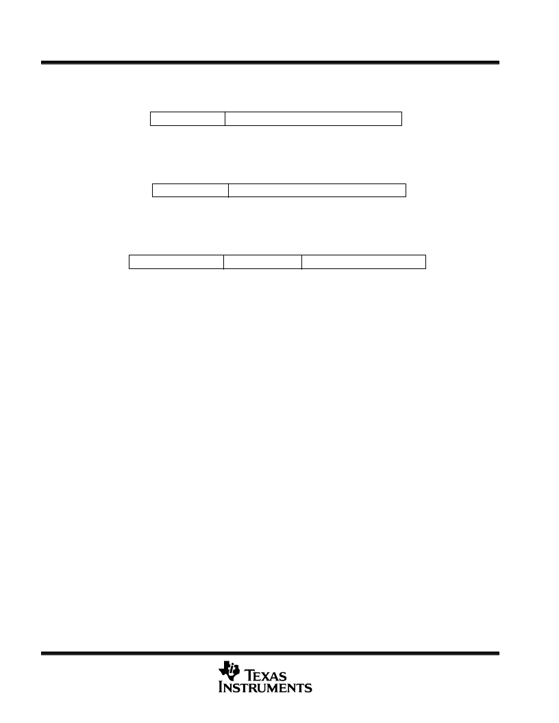
RX DMA word 1 – current-buffer pointer
Unused (bits 31 – 28)
Current-buffer pointer – 16 byte aligned (bits 27 – 0)
The current-buffer pointer is 28 bits, which implies that the buffer is aligned to 16-byte boundaries. This is a
dynamic field that is updated with every RCB-to-SBus transaction.
RX DMA word 2 – start-of-buffer pointer
Unused (bits 31 – 28)
Start-of-buffer pointer – 16 byte aligned (bits 27 – 0)
The start-of-buffer pointer is 28 bits because the buffer is aligned to 16-byte boundaries. This field is copied from
the corresponding 28-bit field in word 0 of a free-buffer-ring entry.
RX DMA word 3 – configuration
Configuration (bits 31 – 23)
Unused (bits 22 – 11)
Null-AAL packet length (bits 10 – 0)
OWN bit position (bit 31)
The OWN bit is set high for each valid receive channel. It is copied into the corresponding OWN bit location in
word 0 at the start of each new packet to indicate that the DMA channel is active.
VC_ON (bit 30)
The VC_ON bit enables packet-reassembly processing. The bit is set in the default mode to indicate that the
VC is enabled. The SAR discards cells received on the corresponding VC when the VC_ON bit is deasserted
on a per-cell basis.
buffer type – small or big (bit 29)
The SAR supports only two buffer sizes on receive: small and big. The host determines the sizes of the small
and big buffers. The buffer-type bit is used to select between a buffer pointer from the small free-buffer ring or
the big free-buffer ring for each new packet, which allows the host to target small or big buffers for all packets
on a given VC. The small free-buffer ring is used when the bit is set and the big free-buffer ring is used in the
default (zero) state.
null-AAL indication (bit 28)
This field is set to indicate that null-AAL packets are received on this BWG (VC). The null-AAL packet-length
field in bits (10 – 0) is used to determine the end of a packet. CRC errors are ignored for null-AAL packets. The
CRC-error indicator in the receive completion ring is not used.
AAL3/4 indication (bit 25)
This field is set to indicate that AAL3/4 packets are received on this BWG (VC). This indicates the EOM field
in byte 6 (bit 6 of an ATM cell is used as the EOP indicator). CRC errors are ignored for AAL3/4 packets. The
CRC-error indicator in the receive completion ring is not used.
end-of-packet wait (bit 24)
This bit must be set to zero by the device driver during initialization. This gives the SAR the responsibility of
setting the bit to one in DMA word 0 (when this feature is enabled). This bit is a status bit used by the TNETA1560
during operation.
相關(guān)PDF資料 |
PDF描述 |
|---|---|
| TNETA1561 | ATM Segmentation and Reassembly Device with PCI Host Interface(ATM 分段和重設(shè)裝置帶SBUS主機(jī)接口) |
| TNETA1600 | SONET/SDH ATM Receiver/Transmitter for 622.08-Mit/s or 155.52-Mbit/s Operation(SONET/SDH ATM接收器/傳送器) |
| TNETA1610 | STS-12c/STM-4 Receiver/Transmitter with Clock Recovery/Generation(STS-12C/STM-4接收/傳送器) |
| TNETA1611 | STS-12c/STM-4 Receiver/Transimitter(STS-12C/STM-4接收/傳送器) |
| TNETA1630 | 622.08-MHz Clock-Recovery Device(622.08-MHz時(shí)鐘發(fā)生裝置) |
相關(guān)代理商/技術(shù)參數(shù) |
參數(shù)描述 |
|---|---|
| TNETA1560MFP | 制造商:Rochester Electronics LLC 功能描述: 制造商:Texas Instruments 功能描述: |
| TNETA1560PGC | 制造商:Rochester Electronics LLC 功能描述:- Bulk |
| TNETA1561PGC | 制造商:Rochester Electronics LLC 功能描述:- Bulk |
| TNETA1570 | 制造商:TI 制造商全稱:Texas Instruments 功能描述:ATM SEGMENTATION AND REASSEMBLY DEVICE WITH INTEGRATED 64-BIT PCI-HOST INTERFACE |
| TNETA1570MFP | 制造商:未知廠家 制造商全稱:未知廠家 功能描述:ATM/SONET Segmentation and Reassembly Circuit |
發(fā)布緊急采購,3分鐘左右您將得到回復(fù)。