- 您現(xiàn)在的位置:買賣IC網(wǎng) > PDF目錄372925 > XPC755BRX400LE Microprocessor PDF資料下載
參數(shù)資料
| 型號: | XPC755BRX400LE |
| 英文描述: | Microprocessor |
| 中文描述: | 微處理器 |
| 文件頁數(shù): | 9/52頁 |
| 文件大小: | 1274K |
| 代理商: | XPC755BRX400LE |
第1頁第2頁第3頁第4頁第5頁第6頁第7頁第8頁當(dāng)前第9頁第10頁第11頁第12頁第13頁第14頁第15頁第16頁第17頁第18頁第19頁第20頁第21頁第22頁第23頁第24頁第25頁第26頁第27頁第28頁第29頁第30頁第31頁第32頁第33頁第34頁第35頁第36頁第37頁第38頁第39頁第40頁第41頁第42頁第43頁第44頁第45頁第46頁第47頁第48頁第49頁第50頁第51頁第52頁
MOTOROLA
MPC755 RISC Microprocessor Hardware Specifications
9
Electrical and Thermal Characteristics
The MPC755 incorporates a thermal management assist unit (TAU) composed of a thermal sensor,
digital-to-analog converter, comparator, control logic, and dedicated special-purpose registers (SPRs). See
the
MPC750 RISC Microprocessor Family User’s Manual
for more information on the use of this feature.
Specifications for the thermal sensor portion of the TAU are found in Table 5.
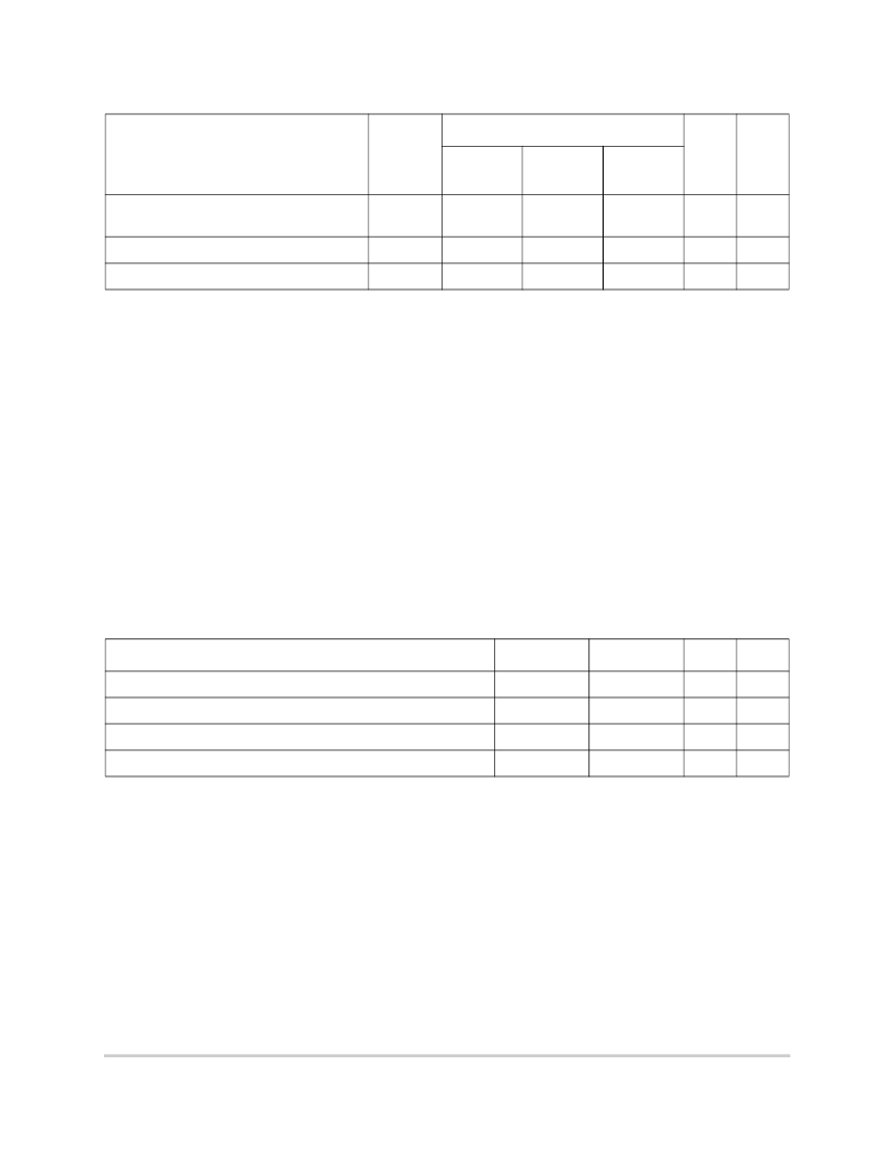
Junction-to-ambient thermal resistance,
200 ft/min airflow, four-layer (2s2p) board
R
θ
JMA
14
21
22
°C/W
1, 3
Junction-to-board thermal resistance
R
θ
JB
8
17
17
°C/W
4
Junction-to-case thermal resistance
R
θ
JC
< 0.1
< 0.1
< 0.1
°C/W
5
Notes:
1. Junction temperature is a function of on-chip power dissipation, package thermal resistance, mounting site
(board) temperature, ambient temperature, air flow, power dissipation of other components on the board, and
board thermal resistance.
2. Per SEMI G38-87 and JEDEC JESD51-2 with the single layer board horizontal.
3. Per JEDEC JESD51-6 with the board horizontal.
4. Thermal resistance between the die and the printed circuit board per JEDEC JESD51-8. Board temperature is
measured on the top surface of the board near the package.
5. Thermal resistance between the die and the case top surface as measured by the cold plate method
(MIL SPEC-883 Method 1012.1) with the calculated case temperature. The actual value of R
θ
JC
for the part is
less than 0.1°C/W.
Refer to Section 1.8.8, “Thermal Management Information,” for more details about thermal management.
Table 5. Thermal Sensor Specifications
At recommended operating conditions (see Table 3)
Characteristic
Min
Max
Unit
Notes
Temperature range
0
127
°C
1
Comparator settling time
20
—
μs
2, 3
Resolution
4
—
°C
3
Accuracy
–12
+12
°C
3
Notes:
1. The temperature is the junction temperature of the die. The thermal assist unit’s raw output does not indicate an
absolute temperature, but must be interpreted by software to derive the absolute junction temperature. For
information about the use and calibration of the TAU, see Motorola Application Note AN1800/D,
Programming the
Thermal Assist Unit in the MPC750 Microprocessor.
2. The comparator settling time value must be converted into the number of CPU clocks that need to be written into
the THRM3 SPR.
3. Guaranteed by design and characterization.
Table 4. Package Thermal Characteristics (continued)
Characteristic
Symbol
Value
Unit
Notes
MPC755
CBGA
MPC755
PBGA
MPC745
PBGA
相關(guān)PDF資料 |
PDF描述 |
|---|---|
| XPC750EC | XPC750P/D XPC750P RISC Microprocessor Hardware Specifications |
| XPC801ZP25 | Microprocessor |
| XPC801ZP40 | Microprocessor |
| XPC821ZP40 | Microprocessor |
| XPC823ZP25 | Microprocessor |
相關(guān)代理商/技術(shù)參數(shù) |
參數(shù)描述 |
|---|---|
| XPC801ZP25 | 制造商:未知廠家 制造商全稱:未知廠家 功能描述:Microprocessor |
| XPC801ZP40 | 制造商:未知廠家 制造商全稱:未知廠家 功能描述:Microprocessor |
| XPC821ZP40 | 制造商:未知廠家 制造商全稱:未知廠家 功能描述:Microprocessor |
| XPC823CVR66B2T | 功能描述:IC MPU POWERQUICC 66MHZ 256-PBGA RoHS:是 類別:集成電路 (IC) >> 嵌入式 - 微處理器 系列:MPC8xx 標(biāo)準(zhǔn)包裝:2 系列:MPC8xx 處理器類型:32-位 MPC8xx PowerQUICC 特點(diǎn):- 速度:133MHz 電壓:3.3V 安裝類型:表面貼裝 封裝/外殼:357-BBGA 供應(yīng)商設(shè)備封裝:357-PBGA(25x25) 包裝:托盤 |
| XPC823CZC66A | 制造商:Freescale Semiconductor 功能描述: |
發(fā)布緊急采購,3分鐘左右您將得到回復(fù)。