- 您現(xiàn)在的位置:買賣IC網(wǎng) > PDF目錄378210 > 80376 (Intel Corp.) 32-BIT Embedded Microprocessor(32位嵌入式微處理器) PDF資料下載
參數(shù)資料
| 型號(hào): | 80376 |
| 廠商: | Intel Corp. |
| 英文描述: | 32-BIT Embedded Microprocessor(32位嵌入式微處理器) |
| 中文描述: | 32位嵌入式微處理器(32位嵌入式微處理器) |
| 文件頁(yè)數(shù): | 36/95頁(yè) |
| 文件大?。?/td> | 1086K |
| 代理商: | 80376 |
第1頁(yè)第2頁(yè)第3頁(yè)第4頁(yè)第5頁(yè)第6頁(yè)第7頁(yè)第8頁(yè)第9頁(yè)第10頁(yè)第11頁(yè)第12頁(yè)第13頁(yè)第14頁(yè)第15頁(yè)第16頁(yè)第17頁(yè)第18頁(yè)第19頁(yè)第20頁(yè)第21頁(yè)第22頁(yè)第23頁(yè)第24頁(yè)第25頁(yè)第26頁(yè)第27頁(yè)第28頁(yè)第29頁(yè)第30頁(yè)第31頁(yè)第32頁(yè)第33頁(yè)第34頁(yè)第35頁(yè)當(dāng)前第36頁(yè)第37頁(yè)第38頁(yè)第39頁(yè)第40頁(yè)第41頁(yè)第42頁(yè)第43頁(yè)第44頁(yè)第45頁(yè)第46頁(yè)第47頁(yè)第48頁(yè)第49頁(yè)第50頁(yè)第51頁(yè)第52頁(yè)第53頁(yè)第54頁(yè)第55頁(yè)第56頁(yè)第57頁(yè)第58頁(yè)第59頁(yè)第60頁(yè)第61頁(yè)第62頁(yè)第63頁(yè)第64頁(yè)第65頁(yè)第66頁(yè)第67頁(yè)第68頁(yè)第69頁(yè)第70頁(yè)第71頁(yè)第72頁(yè)第73頁(yè)第74頁(yè)第75頁(yè)第76頁(yè)第77頁(yè)第78頁(yè)第79頁(yè)第80頁(yè)第81頁(yè)第82頁(yè)第83頁(yè)第84頁(yè)第85頁(yè)第86頁(yè)第87頁(yè)第88頁(yè)第89頁(yè)第90頁(yè)第91頁(yè)第92頁(yè)第93頁(yè)第94頁(yè)第95頁(yè)
376 EMBEDDED PROCESSOR
READY is ignored on the first bus state of all bus
cycles, and sampled each bus state thereafter until
asserted. READY must eventually be asserted to ac-
knowledge every bus cycle, including Halt Indication
and Shutdown Indication bus cycles. When being
sampled, READY must always meet setup and hold
times t
19
and t
20
for correct operation.
Next Address Request (NA)
This is used to request pipelining. This input indi-
cates the system is prepared to accept new values
of BHE, BLE, A
23
–A
1
, W/R, D/C and M/IO from the
80376 even if the end of the current cycle is not
being acknowledged on READY. If this input is ac-
tive when sampled, the next bus cycle’s address and
status signals are driven onto the bus, provided the
next bus request is already pending internally. NA is
ignored in clock cycles in which ADS or READY is
activated. This signal is active LOW and must satisfy
setup and hold times t
15
and t
16
for correct opera-
tion. See
Pipelined Bus Cycles
and
Read and
Write Cycles
for additional information.
BUS ARBITRATION SIGNALS (HOLD, HLDA)
This section describes the mechanism by which the
processor relinquishes control of its local buses
when requested by another bus master device. See
Entering and Exiting Hold Acknowledge
for addi-
tional information.
Bus Hold Request (HOLD)
This input indicates some device other than the
80376 requires bus mastership. When control is
granted, the 80376 floats A
23
–A
1
, BHE, BLE,
D
15
–D
0
, LOCK, M/IO, D/C, W/R and ADS, and
then activates HLDA, thus entering the bus hold ac-
knowledge state. The local bus will remain granted
to the requesting master until HOLD becomes inac-
tive. When HOLD becomes inactive, the 80376 will
deactivate HLDA and drive the local bus (at the
same time), thus terminating the hold acknowledge
condition.
HOLD must remain asserted as long as any other
device is a local bus master. External pull-up resis-
tors may be required when in the hold acknowledge
state since none of the 80376 floated outputs have
internal pull-up resistors. See
Resistor Recommen-
dations
for additional information. HOLD is not rec-
ognized while RESET is active but is recognized dur-
ing the time between the high-to-low transistion of
RESET and the first instruction fetch. If RESET is
asserted while HOLD is asserted, RESET has priori-
ty and places the bus into an idle state, rather than
the hold acknowledge (high-impedance) state.
HOLD is a level-sensitive, active HIGH, synchronous
input. HOLD signals must always meet setup and
hold times t
23
and t
24
for correct operation.
Bus Hold Acknowledge (HLDA)
When active (HIGH), this output indicates the 80376
has relinquished control of its local bus in response
to an asserted HOLD signal, and is in the bus Hold
Acknowledge state.
The Bus Hold Acknowledge state offers near-com-
plete signal isolation. In the Hold Acknowledge
state, HLDA is the only signal being driven by the
80376. The other output signals or bidirectional sig-
nals (D
15
–D
0
, BHE, BLE, A
23
–A
1
, W/R, D/C, M/IO,
LOCK and ADS) are in a high-impedance state so
the requesting bus master may control them. These
pins remain OFF throughout the time that HLDA re-
mains active (see Table 4.3). Pull-up resistors may
be desired on several signals to avoid spurious ac-
tivity when no bus master is driving them. See
Re-
sistor Recommendations
for additional informa-
tion.
When the HOLD signal is made inactive, the 80376
will deactivate HLDA and drive the bus. One rising
edge on the NMI input is remembered for processing
after the HOLD input is negated.
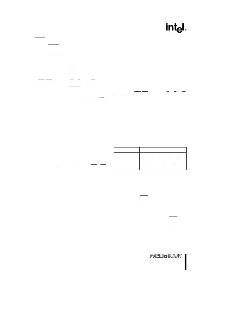
Table 4.3. Output Pin State during HOLD
Pin Value
Pin Names
1
Float
HLDA
LOCK, M/IO, D/C, W/R,
ADS, A
23
–A
1
, BHE, BLE,
D
15
–D
0
Hold Latencies
The maximum possible HOLD latency depends on
the software being executed. The actual HOLD la-
tency at any time depends on the current bus activi-
ty, the state of the LOCK signal (internal to the CPU)
activated by the LOCK prefix, and interrupts. The
80376 will not honor a HOLD request until the cur-
rent bus operation is complete.
The 80376 breaks 32-bit data or I/O accesses into 2
internally locked 16-bit bus cycles; the LOCK signal
is not asserted. The 80376 breaks unaligned 16-bit
or 32-bit data or I/O accesses into 2 or 3 internally
locked 16-bit bus cycles. Again the LOCK signal is
not asserted but a HOLD request will not be recog-
nized until the end of the entire transfer.
36
相關(guān)PDF資料 |
PDF描述 |
|---|---|
| 804-2 | RECTIFIERS ASSEMBLIES |
| 804-3 | RECTIFIERS ASSEMBLIES |
| 804-4 | RECTIFIERS ASSEMBLIES |
| 8040AHL | HMOS SINGLE-COMPONENT 8-BIT MICROCONTROLLER |
| 8048AH | HMOS SINGLE-COMPONENT 8-BIT MICROCONTROLLER |
相關(guān)代理商/技術(shù)參數(shù) |
參數(shù)描述 |
|---|---|
| 803760 | 制造商:Schaffner 功能描述:Power Entry Module Filtered M 3 POS 250VAC 3A ST 1 Port 制造商:Schaffner 功能描述:FILTER PERFORMANCE IEC INLET 3A |
| 803761 | 制造商:Schaffner 功能描述:Power Entry Module Filtered M 3 POS 250VAC 6A ST 1 Port 制造商:Schaffner 功能描述:FILTER PERFORMANCE IEC INLET 6A |
| 803762 | 制造商:Schaffner 功能描述:Power Entry Module Filtered M 3 POS 250VAC 10A ST 1 Port 制造商:Schaffner 功能描述:FILTER PERFORMANCE IEC INLET 10A |
| 803763 | 制造商:Schaffner 功能描述:Power Entry Module Filtered M 3 POS 250VAC 1A ST 1 Port 制造商:Schaffner 功能描述:FILTER PERFORM SNAP-IN INLET 1A |
| 803764 | 制造商:Schaffner 功能描述:Power Entry Module Filtered M 3 POS 250VAC 3A ST 1 Port 制造商:Schaffner 功能描述:FILTER PERFORM SNAP-IN INLET 3A |
發(fā)布緊急采購(gòu),3分鐘左右您將得到回復(fù)。