- 您現(xiàn)在的位置:買(mǎi)賣(mài)IC網(wǎng) > PDF目錄378210 > 80376 (Intel Corp.) 32-BIT Embedded Microprocessor(32位嵌入式微處理器) PDF資料下載
參數(shù)資料
| 型號(hào): | 80376 |
| 廠商: | Intel Corp. |
| 英文描述: | 32-BIT Embedded Microprocessor(32位嵌入式微處理器) |
| 中文描述: | 32位嵌入式微處理器(32位嵌入式微處理器) |
| 文件頁(yè)數(shù): | 9/95頁(yè) |
| 文件大小: | 1086K |
| 代理商: | 80376 |
第1頁(yè)第2頁(yè)第3頁(yè)第4頁(yè)第5頁(yè)第6頁(yè)第7頁(yè)第8頁(yè)當(dāng)前第9頁(yè)第10頁(yè)第11頁(yè)第12頁(yè)第13頁(yè)第14頁(yè)第15頁(yè)第16頁(yè)第17頁(yè)第18頁(yè)第19頁(yè)第20頁(yè)第21頁(yè)第22頁(yè)第23頁(yè)第24頁(yè)第25頁(yè)第26頁(yè)第27頁(yè)第28頁(yè)第29頁(yè)第30頁(yè)第31頁(yè)第32頁(yè)第33頁(yè)第34頁(yè)第35頁(yè)第36頁(yè)第37頁(yè)第38頁(yè)第39頁(yè)第40頁(yè)第41頁(yè)第42頁(yè)第43頁(yè)第44頁(yè)第45頁(yè)第46頁(yè)第47頁(yè)第48頁(yè)第49頁(yè)第50頁(yè)第51頁(yè)第52頁(yè)第53頁(yè)第54頁(yè)第55頁(yè)第56頁(yè)第57頁(yè)第58頁(yè)第59頁(yè)第60頁(yè)第61頁(yè)第62頁(yè)第63頁(yè)第64頁(yè)第65頁(yè)第66頁(yè)第67頁(yè)第68頁(yè)第69頁(yè)第70頁(yè)第71頁(yè)第72頁(yè)第73頁(yè)第74頁(yè)第75頁(yè)第76頁(yè)第77頁(yè)第78頁(yè)第79頁(yè)第80頁(yè)第81頁(yè)第82頁(yè)第83頁(yè)第84頁(yè)第85頁(yè)第86頁(yè)第87頁(yè)第88頁(yè)第89頁(yè)第90頁(yè)第91頁(yè)第92頁(yè)第93頁(yè)第94頁(yè)第95頁(yè)
376 EMBEDDED PROCESSOR
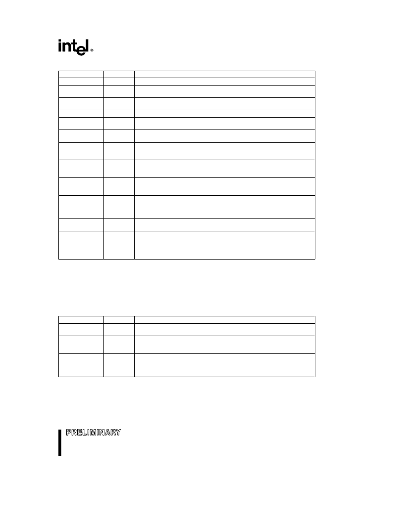
Table 2.1. Flag Definitions
Bit Position
0
2
Name
CF
PF
Function
Carry Flag
DSet on high-order bit carry or borrow; cleared otherwise.
Parity Flag
DSet if low-order 8 bits of result contain an even number
of 1-bits; cleared otherwise.
Auxiliary Carry Flag
DSet on carry from or borrow to the low order
four bits of AL; cleared otherwise.
Zero Flag
DSet if result is zero; cleared otherwise.
Sign Flag
DSet equal to high-order bit of result (0 if positive, 1 if
negative).
Single Step Flag
DOnce set, a single step interrupt occurs after the
next instruction executes. TF is cleared by the single step interrupt.
Interrupt-Enable Flag
DWhen set, external interrupts signaled on the
INTR pin will cause the CPU to transfer control to an interrupt vector
specified location.
Direction Flag
DCauses string instructions to auto-increment (default)
the appropriate index registers when cleared. Setting DF causes auto-
decrement.
Overflow Flag
DSet if the operation resulted in a carry/borrow into
the sign bit (high-order bit) of the result but did not result in a
carry/borrow out of the high-order bit or vice-versa.
I/O Privilege Level
DIndicates the maximum CPL permitted to
execute I/O instructions without generating an exception 13 fault or
consulting the I/O permission bit map. It also indicates the maximum
CPL value allowing alteration of the IF bit.
Nested Task
DIndicates that the execution of the current task is
nested within another task (see
Task Switching
).
Resume Flag
DUsed in conjunction with debug register breakpoints. It
is checked at instruction boundaries before breakpoint processing. If
set, any debug fault is ignored on the next instruction. It is reset at the
successful completion of any instruction except IRET, POPF, and
those instructions causing task switches.
4
AF
6
7
ZF
SF
8
TF
9
IF
10
DF
11
OF
12, 13
IOPL
14
NT
16
RF
CONTROL REGISTER
The 80376 has a 32-bit control register called CR0 that is used to control coprocessor emulation. This register
is shown in Figures, 2.1 and 2.2. The defined CR0 bits are described in Table 2.2. Bits 0, 4 and 31 of CR0 have
fixed values in the 80376. These values cannot be changed. Programs that load CR0 should always load bits
0, 4 and 31 with values previously there to be compatible with the 80386.
Table 2.2. CR0 Definitions
Bit Position
1
Name
MP
Function
Monitor Coprocessor Extension
DAllows WAIT instructions to cause
a processor extension not present exception (number 7).
Emulate Processor Extension
DWhen set, this bit causes a
processor extension not present exception (number 7) on ESC
instructions to allow processor extension emulation.
Task Switched
DWhen set, this bit indicates the next instruction using
a processor extension will cause exception 7, allowing software to test
whether the current processor extension context belongs to the
current task (see
Task Switching
).
2
EM
3
TS
9
相關(guān)PDF資料 |
PDF描述 |
|---|---|
| 804-2 | RECTIFIERS ASSEMBLIES |
| 804-3 | RECTIFIERS ASSEMBLIES |
| 804-4 | RECTIFIERS ASSEMBLIES |
| 8040AHL | HMOS SINGLE-COMPONENT 8-BIT MICROCONTROLLER |
| 8048AH | HMOS SINGLE-COMPONENT 8-BIT MICROCONTROLLER |
相關(guān)代理商/技術(shù)參數(shù) |
參數(shù)描述 |
|---|---|
| 803760 | 制造商:Schaffner 功能描述:Power Entry Module Filtered M 3 POS 250VAC 3A ST 1 Port 制造商:Schaffner 功能描述:FILTER PERFORMANCE IEC INLET 3A |
| 803761 | 制造商:Schaffner 功能描述:Power Entry Module Filtered M 3 POS 250VAC 6A ST 1 Port 制造商:Schaffner 功能描述:FILTER PERFORMANCE IEC INLET 6A |
| 803762 | 制造商:Schaffner 功能描述:Power Entry Module Filtered M 3 POS 250VAC 10A ST 1 Port 制造商:Schaffner 功能描述:FILTER PERFORMANCE IEC INLET 10A |
| 803763 | 制造商:Schaffner 功能描述:Power Entry Module Filtered M 3 POS 250VAC 1A ST 1 Port 制造商:Schaffner 功能描述:FILTER PERFORM SNAP-IN INLET 1A |
| 803764 | 制造商:Schaffner 功能描述:Power Entry Module Filtered M 3 POS 250VAC 3A ST 1 Port 制造商:Schaffner 功能描述:FILTER PERFORM SNAP-IN INLET 3A |
發(fā)布緊急采購(gòu),3分鐘左右您將得到回復(fù)。