- 您現(xiàn)在的位置:買賣IC網(wǎng) > PDF目錄382857 > ARM7TDMI (Electronic Theatre Controls, Inc.) general purpose 32-bit microprocessors PDF資料下載
參數(shù)資料
| 型號: | ARM7TDMI |
| 廠商: | Electronic Theatre Controls, Inc. |
| 英文描述: | general purpose 32-bit microprocessors |
| 中文描述: | 通用32位微處理器 |
| 文件頁數(shù): | 120/268頁 |
| 文件大?。?/td> | 1289K |
| 代理商: | ARM7TDMI |
第1頁第2頁第3頁第4頁第5頁第6頁第7頁第8頁第9頁第10頁第11頁第12頁第13頁第14頁第15頁第16頁第17頁第18頁第19頁第20頁第21頁第22頁第23頁第24頁第25頁第26頁第27頁第28頁第29頁第30頁第31頁第32頁第33頁第34頁第35頁第36頁第37頁第38頁第39頁第40頁第41頁第42頁第43頁第44頁第45頁第46頁第47頁第48頁第49頁第50頁第51頁第52頁第53頁第54頁第55頁第56頁第57頁第58頁第59頁第60頁第61頁第62頁第63頁第64頁第65頁第66頁第67頁第68頁第69頁第70頁第71頁第72頁第73頁第74頁第75頁第76頁第77頁第78頁第79頁第80頁第81頁第82頁第83頁第84頁第85頁第86頁第87頁第88頁第89頁第90頁第91頁第92頁第93頁第94頁第95頁第96頁第97頁第98頁第99頁第100頁第101頁第102頁第103頁第104頁第105頁第106頁第107頁第108頁第109頁第110頁第111頁第112頁第113頁第114頁第115頁第116頁第117頁第118頁第119頁當(dāng)前第120頁第121頁第122頁第123頁第124頁第125頁第126頁第127頁第128頁第129頁第130頁第131頁第132頁第133頁第134頁第135頁第136頁第137頁第138頁第139頁第140頁第141頁第142頁第143頁第144頁第145頁第146頁第147頁第148頁第149頁第150頁第151頁第152頁第153頁第154頁第155頁第156頁第157頁第158頁第159頁第160頁第161頁第162頁第163頁第164頁第165頁第166頁第167頁第168頁第169頁第170頁第171頁第172頁第173頁第174頁第175頁第176頁第177頁第178頁第179頁第180頁第181頁第182頁第183頁第184頁第185頁第186頁第187頁第188頁第189頁第190頁第191頁第192頁第193頁第194頁第195頁第196頁第197頁第198頁第199頁第200頁第201頁第202頁第203頁第204頁第205頁第206頁第207頁第208頁第209頁第210頁第211頁第212頁第213頁第214頁第215頁第216頁第217頁第218頁第219頁第220頁第221頁第222頁第223頁第224頁第225頁第226頁第227頁第228頁第229頁第230頁第231頁第232頁第233頁第234頁第235頁第236頁第237頁第238頁第239頁第240頁第241頁第242頁第243頁第244頁第245頁第246頁第247頁第248頁第249頁第250頁第251頁第252頁第253頁第254頁第255頁第256頁第257頁第258頁第259頁第260頁第261頁第262頁第263頁第264頁第265頁第266頁第267頁第268頁
THUMB Instruction Set
ARM7TDMI Data Sheet
ARM DDI 0029E
5-14
O
5.5.2 Instruction cycle times
All instructions in this format have an equivalent ARM instruction as shown in
·
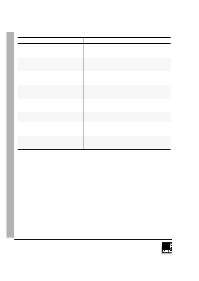
Table
5-6: Summary of format 5 instructions
on page 5-13. The instruction cycle times for the
THUMB instruction are identical to that of the equivalent ARM instruction. For more
information on instruction cycle times, please refer to
·
Chapter 10, Instruction Cycle
Operations
.
5.5.3 The BX instruction
BX performs a Branch to a routine whose start address is specified in a Lo or Hi
register.
Bit 0 of the address determines the processor state on entry to the routine:
Bit 0 = 0
causes the processor to enter ARM state.
Bit 0 = 1
causes the processor to enter THUMB state.
Note
The action of H1 = 1 for this instruction is undefined, and should not be used.
01
0
1
CMP Rd, Hs
CMP Rd, Hs
Compare a register in the range 0-7
with a register in the range 8-15. Set
the condition code flags on the result.
01
1
0
CMP Hd, Rs
CMP Hd, Rs
Compare a register in the range 8-15
with a register in the range 0-7. Set the
condition code flags on the result.
01
1
1
CMP Hd, Hs
CMP Hd, Hs
Compare two registers in the range 8-
15. Set the condition code flags on the
result.
10
0
1
MOV Rd, Hs
MOV Rd, Hs
Move a value from a register in the
range 8-15 to a register in the range 0-
7.
10
1
0
MOV Hd, Rs
MOV Hd, Rs
Move a value from a register in the
range 0-7 to a register in the range 8-
15.
10
1
1
MOV Hd, Hs
MOV Hd, Hs
Move a value between two registers in
the range 8-15.
11
0
0
BX Rs
BX Rs
Perform branch (plus optional state
change) to address in a register in the
range 0-7.
11
0
1
BX Hs
BX Hs
Perform branch (plus optional state
change) to address in a register in the
range 8-15.
Op
H1
H2
THUMB assembler
ARM equivalent
Action
Table 5-6: Summary of format 5 instructions (Continued)
相關(guān)PDF資料 |
PDF描述 |
|---|---|
| AS1431 | Precision Adjustable Shunt Reference |
| AS1431DR4LP13 | Precision Adjustable Shunt Reference |
| AS1431DR4LP7 | Precision Adjustable Shunt Reference |
| AS1431DR4LPA | Precision Adjustable Shunt Reference |
| AS1431DR4LPB | Precision Adjustable Shunt Reference |
相關(guān)代理商/技術(shù)參數(shù) |
參數(shù)描述 |
|---|---|
| ARM7TDMI_G | 制造商:未知廠家 制造商全稱:未知廠家 功能描述:Technical Reference Manual |
| ARM7TDMI-S | 制造商:未知廠家 制造商全稱:未知廠家 功能描述:周立功的中文ARM7TDI文檔 |
| ARM920T | 制造商:未知廠家 制造商全稱:未知廠家 功能描述:System-on-Chip Platform OS Processor |
| ARM940T | 制造商:未知廠家 制造商全稱:未知廠家 功能描述:TECHNICAL REFERENCE MANUAL |
| ARM946E-S | 制造商:未知廠家 制造商全稱:未知廠家 功能描述:ARM946E-S Microprocessor Core with Cache technical manual 6/01 |
發(fā)布緊急采購,3分鐘左右您將得到回復(fù)。