- 您現(xiàn)在的位置:買賣IC網(wǎng) > PDF目錄369945 > P8XC591 (NXP Semiconductors N.V.) HiRel FPGA, Low-Power 1.0?? CMOS Technology PDF資料下載
參數(shù)資料
| 型號: | P8XC591 |
| 廠商: | NXP Semiconductors N.V. |
| 英文描述: | HiRel FPGA, Low-Power 1.0?? CMOS Technology |
| 中文描述: | 單芯片8 - CAN控制器位微控制器 |
| 文件頁數(shù): | 113/160頁 |
| 文件大?。?/td> | 601K |
| 代理商: | P8XC591 |
第1頁第2頁第3頁第4頁第5頁第6頁第7頁第8頁第9頁第10頁第11頁第12頁第13頁第14頁第15頁第16頁第17頁第18頁第19頁第20頁第21頁第22頁第23頁第24頁第25頁第26頁第27頁第28頁第29頁第30頁第31頁第32頁第33頁第34頁第35頁第36頁第37頁第38頁第39頁第40頁第41頁第42頁第43頁第44頁第45頁第46頁第47頁第48頁第49頁第50頁第51頁第52頁第53頁第54頁第55頁第56頁第57頁第58頁第59頁第60頁第61頁第62頁第63頁第64頁第65頁第66頁第67頁第68頁第69頁第70頁第71頁第72頁第73頁第74頁第75頁第76頁第77頁第78頁第79頁第80頁第81頁第82頁第83頁第84頁第85頁第86頁第87頁第88頁第89頁第90頁第91頁第92頁第93頁第94頁第95頁第96頁第97頁第98頁第99頁第100頁第101頁第102頁第103頁第104頁第105頁第106頁第107頁第108頁第109頁第110頁第111頁第112頁當(dāng)前第113頁第114頁第115頁第116頁第117頁第118頁第119頁第120頁第121頁第122頁第123頁第124頁第125頁第126頁第127頁第128頁第129頁第130頁第131頁第132頁第133頁第134頁第135頁第136頁第137頁第138頁第139頁第140頁第141頁第142頁第143頁第144頁第145頁第146頁第147頁第148頁第149頁第150頁第151頁第152頁第153頁第154頁第155頁第156頁第157頁第158頁第159頁第160頁

2000 Jul 26
113
Philips Semiconductors
Preliminary Specification
Single-chip 8-bit microcontroller with CAN controller
P8xC591
16 TIMER 2
16.1
Features of Timer 2
Timer T2 is a 16-bit timer consisting of two registers TMH2
(HIGH byte) and TML2 (LOW byte). The 16-bit
timer/counter can be switched off or clocked via a
prescaler from one of two sources: f
CLK
/6 or an external
signal. When Timer T2 is configured as a counter, the
prescaler is clocked by an external signal on T2 (P3.O). A
rising edge on T2 increments the prescaler, and the
maximum repetition rate is one count per machine cycle
(1 MHz with a 6 MHz oscillator).
The maximum repetition rate for Timer T2 is twice the
maximumrepetitionrateforTimer0andTimer1.T2(P3.0)
is sampled at S2P1 and again at S5P1 (i.e., twice per
machine cycle). A rising edge is detected when T2 is LOW
during one sample and HIGH during the next sample. To
ensure that a rising edge is detected, the input signal must
be LOW for at least
1
2
cycle and then HIGH for at least
1
2
cycle. If a rising edge is detected before the end of S2P1,
the timer will be incremented during the following cycle;
otherwise it will be incremented one cycle later. The
prescaler has a programmable division factor of 1, 2, 4, or
8 and is cleared if its division factor or input source is
changed, or if the timer/counter is reset.
Timer T2 may be read “on the fly” but possesses no extra
read latches, and software precautions may have to be
taken to avoid misinterpretation in the event of an overflow
from least to most significant byte while Timer T2 is being
read. Timer T2 is not loadable and is reset by the RST
signal or by a rising edge on the input signal RT2, if
enabled. RT2 is enabled by setting bit T2ER (TM2CON.5).
When the least significant byte of the timer overflows or
whena16-bitoverflow occurs, aninterrupt requestmay be
generated. Either or both of these overflows can be
programmed to request an interrupt. In both cases, the
interrupt vector will be the same. When the lower byte
(TML2) overflows, flag T2B0 (TM2CON) is set and flag
T20V (TM2lR) is set when TMH2 overflows. These flags
are set one cycle after an overflow occurs. Note that when
T20V is set, T2B0 will also be set. To enable the byte
overflow interrupt, bits ET2 (lEN1.7, enable overflow
interrupt, see Table 67) and T2lS0 (TM2CON.6, byte
overflow interrupt select) must be set. Bit TWBO
(TM2CON.4) is the Timer T2 byte overflow flag. To enable
the 16-bit overflow interrupt, bits ET2 (lE1.7, enable
overflow interrupt) and T2lS1 (TM2CON.7, 16-bit overflow
interrupt select) must be set. Bit T2OV (TM2lR.7) is the
Timer T2 16-bit overflow flag. All interrupt flags must be
resetbysoftware. Toenablebothbyteand 16-bitoverflow,
T2lS0 and T2lS1 must be set and two interrupt service
routines arerequired.Atestontheoverflow flagsindicates
which routine must be executed. For each routine, only the
corresponding overflow flag must be cleared. Timer T2
may be reset by a rising edge on RT2 (P3.1) if the Timer
T2 external reset enable bit (T2ER) in TM2CON is set.
This reset also clears the prescaler. In the Idle mode, the
timer/counter and prescaler are reset and halted. Timer T2
is controlled by the TM2CON special function register (see
Section 16.1.1).
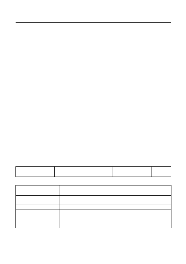
Table 66
Timer T2 Interrupt Enable Register IEN1 (address E8H)
Table 67
Description of interrupt Enable Register IEN1 bits
7
6
5
4
3
2
1
0
ET2
ECAN
ECM1
ECM0
ECT3
ECT2
ECT1
ECT0
BIT
SYMBOL
FUNCTION
7
6
5
4
3
2
1
0
ET2
ECAN
ECM1
ECM0
ECT3
ECT2
ECT1
ECT0
Enable Timer T2 overflow interrupt(s).
Enable CAN interrupt.
Enable T2 Comparator 1 interrupt.
Enable T2 Comparator 0 interrupt.
Enable T2 Capture register 3 interrupt.
Enable T2 Capture register 2 interrupt.
Enable T2 Capture register 1 interrupt.
Enable T2 Capture register 0 interrupt.
相關(guān)PDF資料 |
PDF描述 |
|---|---|
| P90CE201 | 16-bit microcontroller |
| P90CE201AEB | 16-bit microcontroller |
| P9217 | PbS photoconductive detector |
| P930 | CdS photoconductive cell |
| PA025XSB | This technical specification applies to 2.5inch color TFT-LCD panel. |
相關(guān)代理商/技術(shù)參數(shù) |
參數(shù)描述 |
|---|---|
| P8XC592 | 制造商:PHILIPS 制造商全稱:NXP Semiconductors 功能描述:8-bit microcontroller with on-chip CAN |
| P8XCE598 | 制造商:PHILIPS 制造商全稱:NXP Semiconductors 功能描述:8-bit microcontroller with on-chip CAN |
| P8XCL580HFH | 制造商:PHILIPS 制造商全稱:NXP Semiconductors 功能描述:Low voltage 8-bit microcontrollers with UART, I2C-bus and ADC |
| P8XCL580HFT | 制造商:PHILIPS 制造商全稱:NXP Semiconductors 功能描述:Low voltage 8-bit microcontrollers with UART, I2C-bus and ADC |
| P8Z77 DELUXE | 制造商:Asus 功能描述:P8Z77-V Deluxe ATX Motherboard |
發(fā)布緊急采購,3分鐘左右您將得到回復(fù)。