- 您現(xiàn)在的位置:買(mǎi)賣(mài)IC網(wǎng) > PDF目錄377496 > intel386 DX (Intel Corp.) 32-Bit CHMOS Microprocessor With Integrated Memory Management(32位CHMOS 微處理器帶集成存儲(chǔ)管理) PDF資料下載
參數(shù)資料
| 型號(hào): | intel386 DX |
| 廠商: | Intel Corp. |
| 英文描述: | 32-Bit CHMOS Microprocessor With Integrated Memory Management(32位CHMOS 微處理器帶集成存儲(chǔ)管理) |
| 中文描述: | 32位CHMOS微處理器集成內(nèi)存管理(32位CHMOS微處理器帶集成存儲(chǔ)管理) |
| 文件頁(yè)數(shù): | 71/139頁(yè) |
| 文件大小: | 1587K |
| 代理商: | INTEL386 DX |
第1頁(yè)第2頁(yè)第3頁(yè)第4頁(yè)第5頁(yè)第6頁(yè)第7頁(yè)第8頁(yè)第9頁(yè)第10頁(yè)第11頁(yè)第12頁(yè)第13頁(yè)第14頁(yè)第15頁(yè)第16頁(yè)第17頁(yè)第18頁(yè)第19頁(yè)第20頁(yè)第21頁(yè)第22頁(yè)第23頁(yè)第24頁(yè)第25頁(yè)第26頁(yè)第27頁(yè)第28頁(yè)第29頁(yè)第30頁(yè)第31頁(yè)第32頁(yè)第33頁(yè)第34頁(yè)第35頁(yè)第36頁(yè)第37頁(yè)第38頁(yè)第39頁(yè)第40頁(yè)第41頁(yè)第42頁(yè)第43頁(yè)第44頁(yè)第45頁(yè)第46頁(yè)第47頁(yè)第48頁(yè)第49頁(yè)第50頁(yè)第51頁(yè)第52頁(yè)第53頁(yè)第54頁(yè)第55頁(yè)第56頁(yè)第57頁(yè)第58頁(yè)第59頁(yè)第60頁(yè)第61頁(yè)第62頁(yè)第63頁(yè)第64頁(yè)第65頁(yè)第66頁(yè)第67頁(yè)第68頁(yè)第69頁(yè)第70頁(yè)當(dāng)前第71頁(yè)第72頁(yè)第73頁(yè)第74頁(yè)第75頁(yè)第76頁(yè)第77頁(yè)第78頁(yè)第79頁(yè)第80頁(yè)第81頁(yè)第82頁(yè)第83頁(yè)第84頁(yè)第85頁(yè)第86頁(yè)第87頁(yè)第88頁(yè)第89頁(yè)第90頁(yè)第91頁(yè)第92頁(yè)第93頁(yè)第94頁(yè)第95頁(yè)第96頁(yè)第97頁(yè)第98頁(yè)第99頁(yè)第100頁(yè)第101頁(yè)第102頁(yè)第103頁(yè)第104頁(yè)第105頁(yè)第106頁(yè)第107頁(yè)第108頁(yè)第109頁(yè)第110頁(yè)第111頁(yè)第112頁(yè)第113頁(yè)第114頁(yè)第115頁(yè)第116頁(yè)第117頁(yè)第118頁(yè)第119頁(yè)第120頁(yè)第121頁(yè)第122頁(yè)第123頁(yè)第124頁(yè)第125頁(yè)第126頁(yè)第127頁(yè)第128頁(yè)第129頁(yè)第130頁(yè)第131頁(yè)第132頁(yè)第133頁(yè)第134頁(yè)第135頁(yè)第136頁(yè)第137頁(yè)第138頁(yè)第139頁(yè)
Intel386
TM
DX MICROPROCESSOR
use pipelined address with 16-bit memories then
BE0
Y
–BE3
Y
and W/R
Y
are also decoded to de-
termine when BS16
Y
should be asserted. See
5.4.3.6 Pipelined Address with Dynamic Data Bus
Sizing
.)
A2–A31 are directly usable for addressing 32-bit
and 16-bit devices. To address 16-bit devices, A1
and two byte enable signals are also needed.
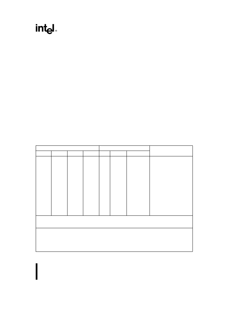
To generate an A1 signal and two Byte Enable sig-
nals for 16-bit access, BE0
Y
–BE3
Y
should be de-
coded as in Table 5-7. Note certain combinations of
BE0
Y
–BE3
Y
are never generated by the Intel386
DX, leading to ‘‘don’t care’’ conditions in the decod-
er. Any BE0
Y
–BE3
Y
decoder, such as Figure 5-7,
may use the non-occurring BE0
Y
–BE3
Y
combina-
tions to its best advantage.
5.3.6 Operand Alignment
With the flexibility of memory addressing on the In-
tel386 DX, it is possible to transfer a logical operand
that spans more than one physical Dword or word of
memory
or
I/O.
Examples
are
32-bit
Dword
operands beginning at addresses not evenly divisi-
ble by 4, or a 16-bit word operand split between two
physical Dwords of the memory array.
Operand alignment and data bus size dictate when
multiple bus cycles are required. Table 5-8 describes
the transfer cycles generated for all combinations of
logical operand lengths, alignment, and data bus siz-
ing. When multiple bus cycles are required to trans-
fer a multi-byte logical operand, the highest-order
bytes are transferred first (but if BS16
Y
asserted
requires two 16-bit cycles be performed, that part of
the transfer is low-order first).
5.4 BUS FUNCTIONAL DESCRIPTION
5.4.1 Introduction
The Intel386 DX has separate, parallel buses for
data and address. The data bus is 32-bits in width,
and bidirectional. The address bus provides a 32-bit
value using 30 signals for the 30 upper-order ad-
dress bits and 4 Byte Enable signals to directly indi-
cate the active bytes. These buses are interpreted
and controlled via several associated definition or
control signals.
Table 5-7. Generating A1, BHE
Y
and BLE
Y
for Addressing 16-Bit Devices
Intel386
TM
DX Signals
16-Bit Bus Signals
Comments
BE3
Y
H
*
H
H
H
H
H
*
H
H
L
L
*
L
*
L
*
L
L
*
L
L
BE2
Y
H
*
H
H
H
L
L
*
L
L
H
H
*
H
*
H
*
L
L
*
L
L
BE1
Y
H
*
H
L
L
H
H
*
L
L
H
H
*
L
*
L
*
H
H
*
L
L
BE0
Y
H
*
L
H
L
H
L
*
H
L
H
L
*
H
*
L
*
H
L
*
H
L
A1
BHE
Y
BLE
Y
(A0)
x
L
L
L
H
x
L
L
H
x
x
x
H
x
L
L
x
H
L
L
H
x
L
L
L
x
x
x
L
x
L
L
x
L
H
L
L
x
H
L
H
x
x
x
L
x
H
L
xDno active bytes
xDnot contiguous bytes
xDnot contiguous bytes
xDnot contiguous bytes
xDnot contiguous bytes
xDnot continguous bytes
BLE
Y
asserted when D0–D7 of 16-bit bus is active.
BHE
Y
asserted when D8–D15 of 16-bit bus is active.
A1 low for all even words; A1 high for all odd words.
Key:
x
e
don’t care
H
e
high voltage level
L
e
low voltage level
*
e
a non-occurring pattern of Byte Enables; either none are asserted,
or the pattern has Byte Enables asserted for non-contiguous bytes
71
相關(guān)PDF資料 |
PDF描述 |
|---|---|
| Intel386 EX | Highly Integrated, 32-Bit, Fully Static Embedded Micropocessor(32位高集成完全靜態(tài)嵌入式微處理器) |
| INTEL386 SXSA | 5-V 32-Bit Fully Static Embedded Microprocessor(5V,32位完全靜態(tài)嵌入式微處理器) |
| intel386 SX | 32-Bit CPU With a 16-Bit External Data Bus And a 24-bit External Address Bus(帶16位內(nèi)部數(shù)據(jù)總線(xiàn)和24位內(nèi)部地址總線(xiàn)32位微處理器) |
| INTEL386 | Intel386 EX Embedded Microprocessor |
| Intel387 dx | DX Math Coprocessor(32位數(shù)學(xué)協(xié)處理器) |
相關(guān)代理商/技術(shù)參數(shù) |
參數(shù)描述 |
|---|---|
| INTEL386SX | 制造商:INTEL 制造商全稱(chēng):Intel Corporation 功能描述:MICROPROCESSOR |
| INTEL387 | 制造商:INTEL 制造商全稱(chēng):Intel Corporation 功能描述:Intel387TM SX MATH COPROCESSOR |
| INTEL387DX | 制造商:未知廠家 制造商全稱(chēng):未知廠家 功能描述:Intel387 DX - MATH COPROCESSOR |
| INTEL387SX | 制造商:INTEL 制造商全稱(chēng):Intel Corporation 功能描述:Intel387 SX - MATH COPROCESSOR |
| INTEL387TMDX | 制造商:INTEL 制造商全稱(chēng):Intel Corporation 功能描述:Intel387TM DX MATH COPROCESSOR |
發(fā)布緊急采購(gòu),3分鐘左右您將得到回復(fù)。