- 您現(xiàn)在的位置:買賣IC網(wǎng) > PDF目錄367908 > PERICOMPI7C8150 (Pericom Semiconductor Corp.) 2-Port PCI-to-PCI Bridge PDF資料下載
參數(shù)資料
| 型號(hào): | PERICOMPI7C8150 |
| 廠商: | Pericom Semiconductor Corp. |
| 英文描述: | 2-Port PCI-to-PCI Bridge |
| 中文描述: | 2端口PCI至PCI橋 |
| 文件頁數(shù): | 31/106頁 |
| 文件大小: | 904K |
| 代理商: | PERICOMPI7C8150 |
第1頁第2頁第3頁第4頁第5頁第6頁第7頁第8頁第9頁第10頁第11頁第12頁第13頁第14頁第15頁第16頁第17頁第18頁第19頁第20頁第21頁第22頁第23頁第24頁第25頁第26頁第27頁第28頁第29頁第30頁當(dāng)前第31頁第32頁第33頁第34頁第35頁第36頁第37頁第38頁第39頁第40頁第41頁第42頁第43頁第44頁第45頁第46頁第47頁第48頁第49頁第50頁第51頁第52頁第53頁第54頁第55頁第56頁第57頁第58頁第59頁第60頁第61頁第62頁第63頁第64頁第65頁第66頁第67頁第68頁第69頁第70頁第71頁第72頁第73頁第74頁第75頁第76頁第77頁第78頁第79頁第80頁第81頁第82頁第83頁第84頁第85頁第86頁第87頁第88頁第89頁第90頁第91頁第92頁第93頁第94頁第95頁第96頁第97頁第98頁第99頁第100頁第101頁第102頁第103頁第104頁第105頁第106頁
PI7C8150
2-PORT PCI-TO-PCI BRIDGE
ADVANCE INFORMATION
21
August 22, 2002 – Revision 1.02
Leaves unchanged the function number and register number fields.
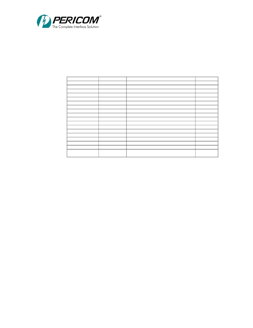
PI7C8150 asserts a unique address line based on the device number. These address lines
may be used as secondary bus IDSEL signals. The mapping of the address lines depends on
the device number in the Type 1 address bits P_AD[15:11]. Table 4–6 presents the
mapping that PI7C8150 uses.
Table 4-6. Device Number to IDSEL S_AD Pin Mapping
Device Number
P_AD[15:11]
0h
00000
1h
00001
2h
00010
3h
00011
4h
00100
5h
00101
6h
00110
7h
00111
8h
01000
9h
01001
Ah
01010
Bh
01011
Ch
01100
Dh
01101
Eh
01110
Fh
01111
10h – 1Eh
10000 – 11110
1Fh
11111
Secondary IDSEL S_AD[31:16]
0000 0000 0000 0001
0000 0000 0000 0010
0000 0000 0000 0100
0000 0000 0000 1000
0000 0000 0001 0000
0000 0000 0010 0000
0000 0000 0100 0000
0000 0000 1000 0000
0000 0001 0000 0000
0000 0010 0000 0000
0000 0100 0000 0000
0000 1000 0000 0000
0001 0000 0000 0000
0010 0000 0000 0000
0100 0000 0000 0000
1000 0000 0000 0000
0000 0000 0000 0000
Generate special cycle (P_AD[7:2] = 00h)
0000 0000 0000 0000 (P_AD[7:2] = 00h)
S_AD
16
17
18
19
20
21
22
23
24
25
26
27
28
29
30
31
-
-
PI7C8150 can assert up to 9 unique address lines to be used as IDSEL signals for
up to 9 devices on the secondary bus, for device numbers ranging from 0 through 8.
Because of electrical loading constraints of the PCI bus, more than 9 IDSEL signals should
not be necessary. However, if device numbers greater than 9 are desired, some external
method of generating IDSEL lines must be used, and no upper address bits are then
asserted. The configuration transaction is still translated and passed from the primary bus to
the secondary bus. If no IDSEL pin is asserted to a secondary device, the transaction ends
in a master abort.
PI7C8150 forwards Type 1 to Type 0 configuration read or write transactions as delayed
transactions. Type 1 to Type 0 configuration read or write transactions are limited to a
single 32-bit data transfer.
3.7.3
TYPE 1 TO TYPE 1 FORWARDING
Type 1 to Type 1 transaction forwarding provides a hierarchical configuration mechanism
when two or more levels of PCI-to-PCI bridges are used.
When PI7C8150 detects a Type 1 configuration transaction intended for a PCI bus
downstream from the secondary bus, PI7C8150 forwards the transaction unchanged to the
secondary bus. Ultimately, this transaction is translated to a Type 0 configuration command
or to a special cycle transaction by a downstream PCI-to-PCI bridge. Downstream Type 1
to Type 1 forwarding occurs when the following conditions are met during the address
phase:
The lowest two address bits are equal to 01b.
相關(guān)PDF資料 |
PDF描述 |
|---|---|
| PESDXL2BT | Low capacitance double bidirectional ESD protection diodes in SOT23 |
| PESDXL2UM | LJT 23C 21#20 2#16 PIN RECP |
| PETAM1270BK300R | BRAID SLEEVING 300M |
| PETAM1270BK50C | 5V RS232 Transceiver with One Receiver Active in SHUTDOWN |
| PETAM1901BK200R | BRAID SLEEVING 300M |
相關(guān)代理商/技術(shù)參數(shù) |
參數(shù)描述 |
|---|---|
| PERINCSPRT5PKM | 制造商:Dialogic Corporation 功能描述:SERVICE;5PK;PERINCIDENT;HW;SUP |
| PER-M18 | 制造商:AAEON 制造商全稱:AAEON 功能描述:Desktop Stand For ONYX-150/ 153/ 154/ 172/ 192/ 1722/ 1922/ 2122/ 2215 (VESA 100) |
| PER-M20 | 制造商:AAEON 制造商全稱:AAEON 功能描述:Desktop Stand For ONYX-170/ 172/ 173/ 174/ 175/ 175S/175X/ 175V/ 190/ 192/ 193/ 195/ 195S/ 195X/195V/ 1722/ 1922/ 2122/ 2217/ 2219 (VESA 100/75) |
| PERMARK-FB-1/2-1.50-9 | 制造商:TE Connectivity 功能描述:PERMARK-FB-1/2-1.50-9 |
| PERMARK-FB-1/2-NO.21-9 | 制造商:TE Connectivity 功能描述:PERMARK-FB-1/2-NO.21-9 |
發(fā)布緊急采購,3分鐘左右您將得到回復(fù)。