- 您現(xiàn)在的位置:買賣IC網(wǎng) > PDF目錄371179 > T8100A H.100/H.110 Interface and Time-Slot Interchangers PDF資料下載
參數(shù)資料
| 型號: | T8100A |
| 英文描述: | H.100/H.110 Interface and Time-Slot Interchangers |
| 中文描述: | H.100/H.110接口和時(shí)隙Interchangers |
| 文件頁數(shù): | 75/112頁 |
| 文件大小: | 1408K |
| 代理商: | T8100A |
第1頁第2頁第3頁第4頁第5頁第6頁第7頁第8頁第9頁第10頁第11頁第12頁第13頁第14頁第15頁第16頁第17頁第18頁第19頁第20頁第21頁第22頁第23頁第24頁第25頁第26頁第27頁第28頁第29頁第30頁第31頁第32頁第33頁第34頁第35頁第36頁第37頁第38頁第39頁第40頁第41頁第42頁第43頁第44頁第45頁第46頁第47頁第48頁第49頁第50頁第51頁第52頁第53頁第54頁第55頁第56頁第57頁第58頁第59頁第60頁第61頁第62頁第63頁第64頁第65頁第66頁第67頁第68頁第69頁第70頁第71頁第72頁第73頁第74頁當(dāng)前第75頁第76頁第77頁第78頁第79頁第80頁第81頁第82頁第83頁第84頁第85頁第86頁第87頁第88頁第89頁第90頁第91頁第92頁第93頁第94頁第95頁第96頁第97頁第98頁第99頁第100頁第101頁第102頁第103頁第104頁第105頁第106頁第107頁第108頁第109頁第110頁第111頁第112頁
Lucent Technologies Inc.
71
Advance Data Sheet
November 1999
H.100/H.110 Interfaces and Time-Slot Interchangers
Ambassador T8100A, T8102, and T8105
3 Using the TSI Devices
(continued)
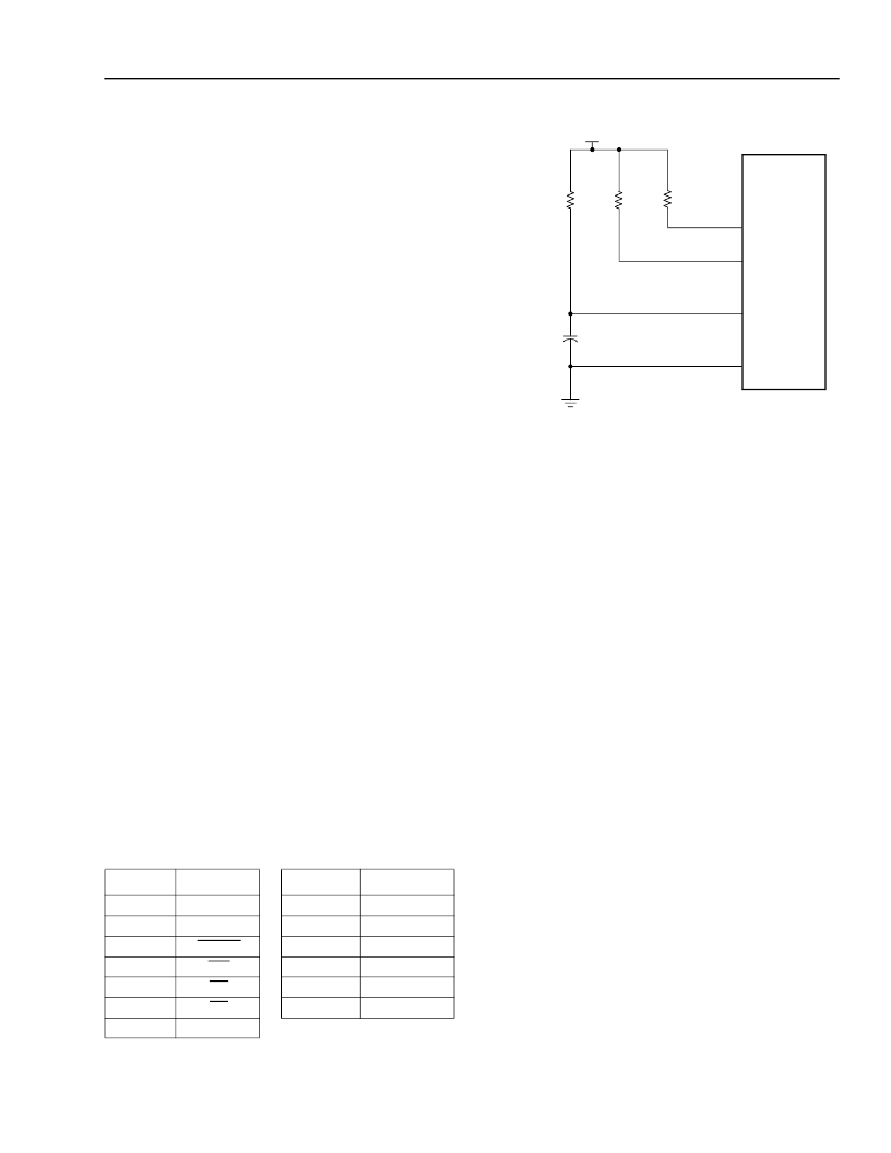
3.3 Basic Connections
At a minimum, the devices require power, ground, and
a 16.384 MHz crystal (or 16.384 MHz oscillator). It is
also recommended that the internal PLLs be treated as
other analog circuits are, so the user should provide
the appropriate filtering between the PLL1V
DD
and V
DD
pins (as well as PLL2V
DD
and V
DD
pins). The RDY pin
is operated as an open collector output. It is actively
driven low or into 3-state. The user should apply a pull-
up (e.g., 10 k
) to maintain standard microprocessor
interfacing. It is recommended that the 10 k
be tied to
3.3 V (since the device’s nominal V
OH
is 3.3 V), but the
resistor may also be tied up to 5 V without damaging
the device. A 33
μ
F tantalum capacitor and 25
series
resistor are necessary to provide VCO stability in the
PLLs. PLL connections are shown in Figure 20.
3.3.1 LPUE Control Pins
A list of 46 pull-ups which LPUE controls is shown in
the table below. LPUE has a pull-up attached, so the
default is pull-ups enabled.
LPUE is used as an assist to meet the CompactPCI*
Hot Swap specification. During live insertion/removal,
the only devices that should be on are the power man-
ager and interface parts (PCI interface attached to
J1, H.110 interface attached to J4 on a CompactPCI
chassis). Without the LPUE, anything connected to the
T810x would get current flow from the early power
through the pull-up resistors. When those parts power-
up (late power), they already have current flowing
through the I/O and latch-up may occur. Quick-switch
parts were used for isolation on the earlier T8100
device, so when the T8100A/02/05 were designed,
LPUE was added to break the current flow and elimi-
nate the isolation switches. LPUE is typically tied to a
pin on the CompactPCIpower manager so that the pull
ups are re-enabled with backside power turning on.
Table 68. LPUE Control Pins
5-6114.aF
Figure 20. External Connection to PLLs
3.3.2 H.100/H.110 Data Pin Series Termination
All data bus lines must have a 24
series resistor,
even if only data lines 16—31 are used.
3.3.3 H.110 Hot Swap
When using the Ambassadorin a hot-swap application,
it is acceptable to power the PLLs after applying power
to the chip. All hot-swap requirements are governed by
the CompactPCIHot Swap specification.
* CompactPCI is a registered trademark of the PCI Industrial Com-
puter Manufacturers Group.
Pin
1
Name
3MHzIn
D[7:0]
Pin
54
64
65
Name
4MHzIn
FromDJAT
ToDJAT
GP[5:0]
LDI[7:0]
LDI[15:8]
22—15
24
26
27
28
45—38
RESET
WR
RD
CS
L_REF[7:0]
66—71
192—185
201—194
T8100A
T8102
T8105
RDY
PLLV
DDS
PLLGND
S
V
DD
= 3.3 V
25
TANTALUM
10 k
50 k
NETREF,
C8s, AND
FRAMES
33
μ
F
相關(guān)PDF資料 |
PDF描述 |
|---|---|
| T8102A | H.100/H.110 Interface and Time-Slot Interchangers |
| T8105A | H.100/H.110 Interface and Time-Slot Interchangers |
| T8100 | H.100/H.110 Interface and Time-Slot Interchanger |
| T8110 | Version History |
| T8301 | T8301 Internet Protocol Telephone Phone-On-A-Chip⑩ IP Solution DSP |
相關(guān)代理商/技術(shù)參數(shù) |
參數(shù)描述 |
|---|---|
| T8100A-BAL | 制造商:Alcatel-Lucent 功能描述:ELECTRONIC COMPONENT |
| T8100A-BAL4DB | 制造商:AGERE 功能描述: |
| T8100-D | 制造商:GE Sensing & Inspection Technologies 功能描述:CO2/TEMP SENS WALL MNT DUAL OUT |
| T8100-E | 制造商:GE Sensing & Inspection Technologies 功能描述:TRANSMITTER, CO2, HUMIDITY, TEMP 制造商:GE MEASUREMENT & CONTROL 功能描述:TRANSMITTER, CO2, HUMIDITY, TEMP; Plug Type:- ;RoHS Compliant: Yes 制造商:GE MEASUREMENT & CONTROL/GE SENSING 功能描述:TRANSMITTER, CO2, HUMIDITY, TEMP; Plug Type:- ;RoHS Compliant: Yes |
| T8100-E-D | 制造商:GE Sensing & Inspection Technologies 功能描述:TRANSMITTER, CO2, HUMIDITY, TEMP 制造商:GE MEASUREMENT & CONTROL 功能描述:TRANSMITTER, CO2, HUMIDITY, TEMP; Plug Type:- ;RoHS Compliant: Yes 制造商:GE MEASUREMENT & CONTROL/GE SENSING 功能描述:TRANSMITTER, CO2, HUMIDITY, TEMP; Plug Type:- ;RoHS Compliant: Yes |
發(fā)布緊急采購,3分鐘左右您將得到回復(fù)。