- 您現在的位置:買賣IC網 > PDF目錄370008 > PM2329 Telecommunication IC PDF資料下載
參數資料
| 型號: | PM2329 |
| 英文描述: | Telecommunication IC |
| 中文描述: | 通信集成電路 |
| 文件頁數: | 56/162頁 |
| 文件大?。?/td> | 1581K |
| 代理商: | PM2329 |
第1頁第2頁第3頁第4頁第5頁第6頁第7頁第8頁第9頁第10頁第11頁第12頁第13頁第14頁第15頁第16頁第17頁第18頁第19頁第20頁第21頁第22頁第23頁第24頁第25頁第26頁第27頁第28頁第29頁第30頁第31頁第32頁第33頁第34頁第35頁第36頁第37頁第38頁第39頁第40頁第41頁第42頁第43頁第44頁第45頁第46頁第47頁第48頁第49頁第50頁第51頁第52頁第53頁第54頁第55頁當前第56頁第57頁第58頁第59頁第60頁第61頁第62頁第63頁第64頁第65頁第66頁第67頁第68頁第69頁第70頁第71頁第72頁第73頁第74頁第75頁第76頁第77頁第78頁第79頁第80頁第81頁第82頁第83頁第84頁第85頁第86頁第87頁第88頁第89頁第90頁第91頁第92頁第93頁第94頁第95頁第96頁第97頁第98頁第99頁第100頁第101頁第102頁第103頁第104頁第105頁第106頁第107頁第108頁第109頁第110頁第111頁第112頁第113頁第114頁第115頁第116頁第117頁第118頁第119頁第120頁第121頁第122頁第123頁第124頁第125頁第126頁第127頁第128頁第129頁第130頁第131頁第132頁第133頁第134頁第135頁第136頁第137頁第138頁第139頁第140頁第141頁第142頁第143頁第144頁第145頁第146頁第147頁第148頁第149頁第150頁第151頁第152頁第153頁第154頁第155頁第156頁第157頁第158頁第159頁第160頁第161頁第162頁

Proprietary and Confidential to PMC-Sierra, Inc and for its Customers
’
Internal Use
Document ID: PMC-2010146, Issue 4
59
PM2329 ClassiPI Network Classification Processor Datasheet
3.1.2 Data Flow
This section presents a brief overview of the data flow of a packet as it is processed. Details of packet
processing are discussed in later sections of this chapter.
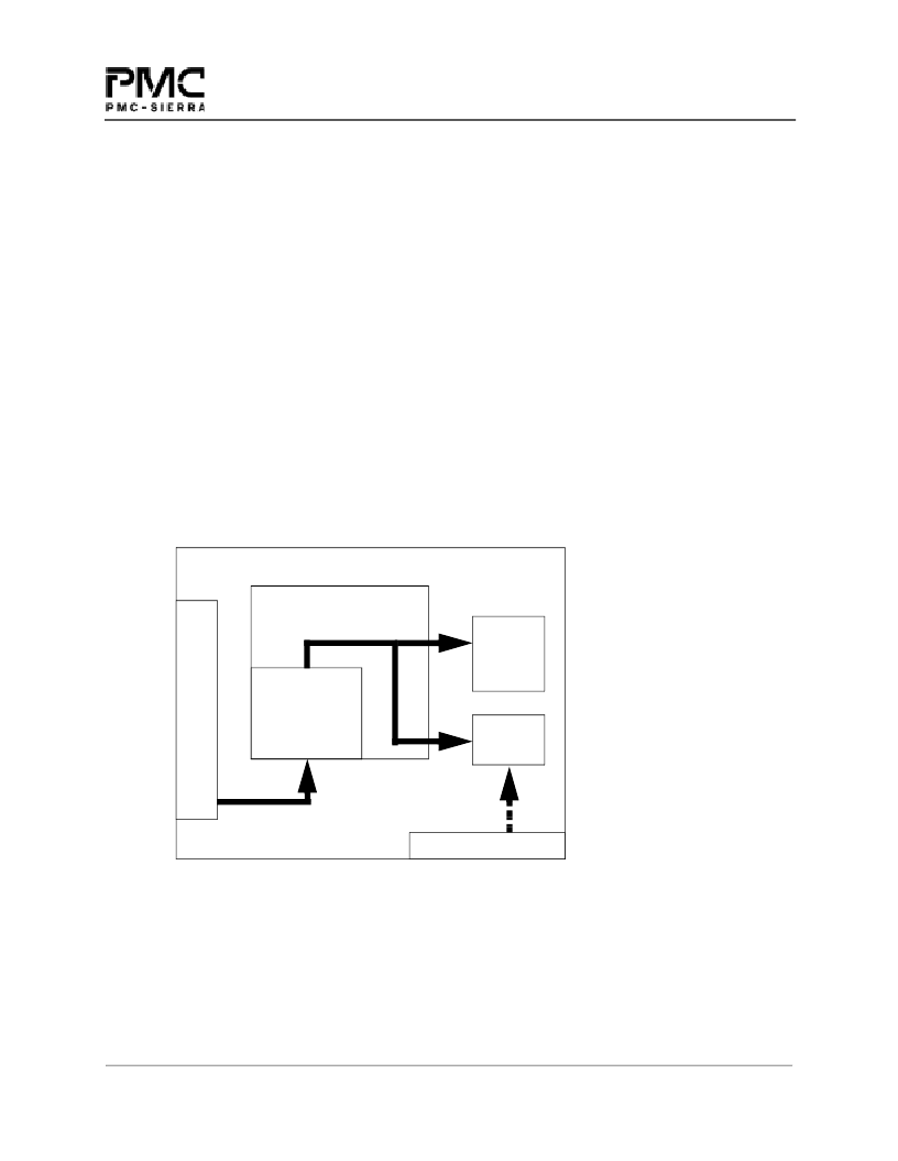
Figure 15 illustrates the data flow for the PM2329 during normal operation. The data flow in the device
can be split into three phases:
Packet Transfer Phase
OC Processing Phase
Result Phase
Packet Transfer Phase
During the Packet Transfer Phase, the packet data and associated control information is transferred to the
device, over the PM2329
’
s system interface. It can be loaded into the PM2329 by a Packet Source (PS), or
directly by the external processor.
The packets are stored in the PM2329 Packet Input Buffer--an input FIFO which is the first element in the
data path inboard from the system interface.
Figure 16 Simplified Data Flow
The Packet Input Buffer
’
s physical size is 256 bytes deep times the total number of channels supported by
the PM2329 (256 x 32 bytes). A Packet Source can load the Packet Input Buffer using either a single write
port (the Packet Buffer Input Register, or PBIR), or alternatively with SRAM-like addressing, wherein a
block memory transfer mechanism is utilized in which the destination address increments.
In single-channel mode, the Packet Input Buffer acts like a FIFO for multiple packets. In multi-channel
mode, several packets may be transferred collectively into the Packet Input Buffer. If a cascade
PM2329
Field Extraction Engine
S
ctl info
Policy
Search
Engine
Control
Unit
Packet
Input
Buffer
E-RAM INTERFACE
相關PDF資料 |
PDF描述 |
|---|---|
| PM239P | Analog Comparator |
| PM30RHC060 | TRANSISTOR | IGBT POWER MODULE | 3-PH BRIDGE | 600V V(BR)CES | 30A I(C) |
| PM3321-QC | DATA CROSS CONNECT|LDCC|84PIN|PLASTIC |
| PM355AJ | Voltage-Feedback Operational Amplifier |
| PM355AZ | Voltage-Feedback Operational Amplifier |
相關代理商/技術參數 |
參數描述 |
|---|---|
| PM233-155.52M | 制造商:CONNOR-WINFIELD 制造商全稱:Connor-Winfield Corporation 功能描述:5.0x7.0mm Surface Mount LVPECL Clock Oscillator Series |
| PM2379-001 | 制造商:Delphi Corporation 功能描述:TAPE MARK WHT |
| PM238 | 制造商:PURDY 制造商全稱:PURDY 功能描述:AC Fans and Blowers |
| PM238-115-1751BT-4 | 制造商:INTERFAN 功能描述:Fan, AC, 115V, 172x150x51mm, Obround, 238CFM, 3100RPM, 55dBA, Terminal Block |
發(fā)布緊急采購,3分鐘左右您將得到回復。