- 您現(xiàn)在的位置:買賣IC網(wǎng) > PDF目錄369939 > P32P4911A (NXP SEMICONDUCTORS) PRML Read Channel with PR4, 8/9 ENDEC, FWR Servo PDF資料下載
參數(shù)資料
| 型號(hào): | P32P4911A |
| 廠商: | NXP SEMICONDUCTORS |
| 元件分類: | 光電元器件 |
| 英文描述: | PRML Read Channel with PR4, 8/9 ENDEC, FWR Servo |
| 中文描述: | 1 CHANNEL READ CHANNEL, PQFP100 |
| 封裝: | 14 X 14 X 1.40 MM, PLASTIC, LQFP-100 |
| 文件頁數(shù): | 12/63頁 |
| 文件大?。?/td> | 257K |
| 代理商: | P32P4911A |
第1頁第2頁第3頁第4頁第5頁第6頁第7頁第8頁第9頁第10頁第11頁當(dāng)前第12頁第13頁第14頁第15頁第16頁第17頁第18頁第19頁第20頁第21頁第22頁第23頁第24頁第25頁第26頁第27頁第28頁第29頁第30頁第31頁第32頁第33頁第34頁第35頁第36頁第37頁第38頁第39頁第40頁第41頁第42頁第43頁第44頁第45頁第46頁第47頁第48頁第49頁第50頁第51頁第52頁第53頁第54頁第55頁第56頁第57頁第58頁第59頁第60頁第61頁第62頁第63頁

1996 Jul 25
12
Philips Semiconductors
Product specification
PRML Read Channel with PR4,
8/9 ENDEC, FWR Servo
P32P4911A
The Viterbi qualifier is implemented as two parallel qualifiers that operate on interleaved samples. Each qualifier has a
survival sequence register length of 5.
To facilitate media scan testing, the Viterbi survival sequence register may be bypassed by setting the BYPSR bit in the
Viterbi Detector Threshold (VDT) register.
Programmable Filter Circuit Description
The on-chip, continuous time, low pass filter has register programmable cutoff and boost settings, and provides both
normal and differentiated outputs. It is a 7th order filter that provides a 0.05
°
phase equiripple response. The group delay
is relatively constant up to twice the cutoff frequency. For pulse slimming two zero programmable boost equalization is
provided with no degradation to the group delay performance. The differentiated output is created by a single-pole,
single-zero differentiator. Both the boost and the filter cutoff frequency for data reads and the filter cutoff frequency for
servo reads are programmed through internal 7-bit DACs, which are accessed via the serial port logic. The nominal
boost range at the cutoff frequency is 0 to 13 dB for data reads and is controlled by the Data Boost Register. In servo
mode, the boost can be programmed in 2 dB steps from 0 to 6 dB by programming the two FBS bits (bits 6 and 7) in the
Filter Boost Servo register. The cutoff frequency, c is variable from 4 to 34 MHz and controlled by the Data Cutoff
Register or Servo Cutoff Register in the servo mode. The cutoff and boost values for servo reads are automatically
switched when servo mode is entered.
The filter zero locations can be programmed asymmetrically about zero to compensate for MR head time asymmetry.
The asymmetry is adjusted by programming the 6 FGD bits (bits 0-5) in the Filter Boost Servo register. The asymmetric
zeros are not usable while in servo mode.
The normal low pass filter is of a seven-pole two-real-zero type. Figure 5 illustrates the transfer function normalized to
1 rad/s. The response can be denormalized to the cutoff frequency of
c (Hz) by replacing s by s/2
π
c, while the boost
and group delay equalization are controlled by varying the
α
and
β
.
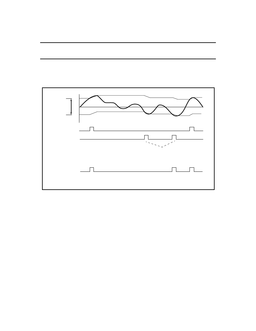
Figure 4: Viterbi Detection
Viterbi
Threshold
WIndow
Viterbi
Detector
Output
+ pulse detect
- pulse detect
For sequential pulses of the same
polarity, the latest is selected by the
survival sequence register logic since
it is always of greater magnitude.
+th
-th
相關(guān)PDF資料 |
PDF描述 |
|---|---|
| P3500SA | SIDACtor Device |
| P3500S | SIDACtor Device |
| P3500SCMC | solid state crowbar devices |
| P3500SD | solid state crowbar devices |
| P3500SC | SIDACtor Device |
相關(guān)代理商/技術(shù)參數(shù) |
參數(shù)描述 |
|---|---|
| P32P4F-F | 制造商:TE Connectivity 功能描述: |
| P32RIGIDT | 制造商:Brady Corporation 功能描述:SIGN NO UNAUTHORISED PERSONS 250X200 |
| P32-S | 制造商:Linemaster Switch Corporation 功能描述:Premier |
| P32W2A2-100-7 | 功能描述:膠帶 Acrylic Foam Tape 1/32" x 1" x 7YD RoHS:否 制造商:3M Electronic Specialty 產(chǎn)品:Tapes 類型:Shielding 描述/功能:EMI/RFI Foil Shielding Tape 顏色: 材料:Copper Foil 寬度:1 in x 18 yds |
| P32W2A2-100-72 | 功能描述:膠帶 Acrylic Foam Tape 1/32" x 1" x 72YD RoHS:否 制造商:3M Electronic Specialty 產(chǎn)品:Tapes 類型:Shielding 描述/功能:EMI/RFI Foil Shielding Tape 顏色: 材料:Copper Foil 寬度:1 in x 18 yds |
發(fā)布緊急采購,3分鐘左右您將得到回復(fù)。