- 您現(xiàn)在的位置:買賣IC網(wǎng) > PDF目錄377000 > DSP16210 TVS 400W 6.5V UNIDIRECT SMA PDF資料下載
參數(shù)資料
| 型號(hào): | DSP16210 |
| 英文描述: | TVS 400W 6.5V UNIDIRECT SMA |
| 中文描述: | DSP16210數(shù)字信號(hào)處理器 |
| 文件頁(yè)數(shù): | 56/173頁(yè) |
| 文件大小: | 2621K |
| 代理商: | DSP16210 |
第1頁(yè)第2頁(yè)第3頁(yè)第4頁(yè)第5頁(yè)第6頁(yè)第7頁(yè)第8頁(yè)第9頁(yè)第10頁(yè)第11頁(yè)第12頁(yè)第13頁(yè)第14頁(yè)第15頁(yè)第16頁(yè)第17頁(yè)第18頁(yè)第19頁(yè)第20頁(yè)第21頁(yè)第22頁(yè)第23頁(yè)第24頁(yè)第25頁(yè)第26頁(yè)第27頁(yè)第28頁(yè)第29頁(yè)第30頁(yè)第31頁(yè)第32頁(yè)第33頁(yè)第34頁(yè)第35頁(yè)第36頁(yè)第37頁(yè)第38頁(yè)第39頁(yè)第40頁(yè)第41頁(yè)第42頁(yè)第43頁(yè)第44頁(yè)第45頁(yè)第46頁(yè)第47頁(yè)第48頁(yè)第49頁(yè)第50頁(yè)第51頁(yè)第52頁(yè)第53頁(yè)第54頁(yè)第55頁(yè)當(dāng)前第56頁(yè)第57頁(yè)第58頁(yè)第59頁(yè)第60頁(yè)第61頁(yè)第62頁(yè)第63頁(yè)第64頁(yè)第65頁(yè)第66頁(yè)第67頁(yè)第68頁(yè)第69頁(yè)第70頁(yè)第71頁(yè)第72頁(yè)第73頁(yè)第74頁(yè)第75頁(yè)第76頁(yè)第77頁(yè)第78頁(yè)第79頁(yè)第80頁(yè)第81頁(yè)第82頁(yè)第83頁(yè)第84頁(yè)第85頁(yè)第86頁(yè)第87頁(yè)第88頁(yè)第89頁(yè)第90頁(yè)第91頁(yè)第92頁(yè)第93頁(yè)第94頁(yè)第95頁(yè)第96頁(yè)第97頁(yè)第98頁(yè)第99頁(yè)第100頁(yè)第101頁(yè)第102頁(yè)第103頁(yè)第104頁(yè)第105頁(yè)第106頁(yè)第107頁(yè)第108頁(yè)第109頁(yè)第110頁(yè)第111頁(yè)第112頁(yè)第113頁(yè)第114頁(yè)第115頁(yè)第116頁(yè)第117頁(yè)第118頁(yè)第119頁(yè)第120頁(yè)第121頁(yè)第122頁(yè)第123頁(yè)第124頁(yè)第125頁(yè)第126頁(yè)第127頁(yè)第128頁(yè)第129頁(yè)第130頁(yè)第131頁(yè)第132頁(yè)第133頁(yè)第134頁(yè)第135頁(yè)第136頁(yè)第137頁(yè)第138頁(yè)第139頁(yè)第140頁(yè)第141頁(yè)第142頁(yè)第143頁(yè)第144頁(yè)第145頁(yè)第146頁(yè)第147頁(yè)第148頁(yè)第149頁(yè)第150頁(yè)第151頁(yè)第152頁(yè)第153頁(yè)第154頁(yè)第155頁(yè)第156頁(yè)第157頁(yè)第158頁(yè)第159頁(yè)第160頁(yè)第161頁(yè)第162頁(yè)第163頁(yè)第164頁(yè)第165頁(yè)第166頁(yè)第167頁(yè)第168頁(yè)第169頁(yè)第170頁(yè)第171頁(yè)第172頁(yè)第173頁(yè)

Data Sheet
July 2000
DSP16210 Digital Signal Processor
56
DRAFT COPY
Lucent Technologies Inc.
Hardware Architecture
(continued)
Clock Synthesis
The DSP16210 provides an on-chip programmable clock synthesizer that can be driven by an external clock at a
fraction of the desired instruction rate.
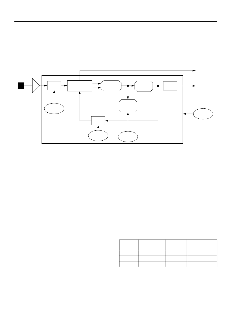
Figure 18
is the synthesizer block diagram, which is based on a phase-lock
loop (PLL). The terms clock synthesizer and PLL are used interchangeably.
Notes:
If PLLEN is set, the PLL is enabled (powered up). If PLLEN is cleared, the PLL is disabled (powered down).
The PLL sets the LOCK flag when its output is stable. The LOCK flag is an input to CORE0 and to CORE1.
Figure 18. Clock Synthesizer (PLL) Block Diagram
Figure 19 on page 57
illustrates the internal clock
selection and disable logic. The clock selection logic
selects the internal clock (CLK) from one of the follow-
ing three clock sources:
I
CKI: This pin is driven by an external oscillator or the
pin’s associated boundary-scan logic under JTAG
control. If CKI is selected as the clock source, then
CLK has the frequency and duty cycle of CKI.
I
PLL: The PLL generates a clock source with a pro-
grammable frequency (an M/2N multiple of the CKI
clock). The PLLs output is f
PLL
. If the PLL is selected
as the clock source, then CLK has the frequency and
duty cycle of the PLL output f
PLL
.
I
Ring Oscillator: The internal ring oscillator produces
a slow clock that requires no external
stimulus. When the slow clock is selected as the
clock source, then CLK has the frequency and duty
cycle of the ring oscillator output. The core con-
sumes less power when clocked with the slow
clock. See
Table 91 on page 141
for timing charac-
teristics of the ring oscillator.
After device reset, CKI is selected as the default clock
source for the DSP16210. Setting the appropriate bits
in the
pllc
and
powerc
control registers (
Table 64 on
page 105
and
Table 65 on page 106
) enables either the
PLL or the ring oscillator to become the clock source.
Table 28
defines the selection of the three clock
sources as a function of the PLLSEL field (bit 14 of
pllc
) and the SLOWCLK field (bit 10 of
powerc
).
Table 28. Clock Source Selection
PLLSEL
(pllc[14])
(powerc[10])
0
0
1
The clock disable logic provides several methods for
shutting off the internal clock to save power. See
Power Management beginning on page 61
for details.
LOCK
PLL
f
CKI
Nbits[2:0]
(pllc[7:5])
Mbits[4:0]
(pllc[4:0])
LF[3:0]
(pllc[11:8])
÷
M
÷
N
PHASE
DETECTOR
LOOP
FILTER
CHARGE
PUMP
VCO
CKI
f
PLL
PLLEN
(pllc[15])
÷
2
SLOWCLK
f
CLK
Description
0
1
X
f
CKI
CKI pin
f
SLOW CLOCK
Ring Oscillator
f
PLL
PLL
相關(guān)PDF資料 |
PDF描述 |
|---|---|
| DSP1627 | TVS 400W 6.5V BIDIRECT SMA |
| DSP1629 | TVS 400W 64V UNIDIRECT SMA |
| DSP16410C | TVS 400W 7.0V UNIDIRECT SMA |
| DSP16410 | 16-bit fixed point DSP with Flash |
| DSP25-16AR | Phase-leg Rectifier Diode |
相關(guān)代理商/技術(shù)參數(shù) |
參數(shù)描述 |
|---|---|
| DSP1627 | 制造商:AGERE 制造商全稱:AGERE 功能描述:DSP1627 Digital Signal Processor |
| DSP1627F32K10IR | 制造商:未知廠家 制造商全稱:未知廠家 功能描述:DSP|16-BIT|CMOS|QFP|100PIN|PLASTIC |
| DSP1627F32K10IT | 制造商:未知廠家 制造商全稱:未知廠家 功能描述:DSP|16-BIT|CMOS|QFP|100PIN|PLASTIC |
| DSP1627F32K11I | 制造商:未知廠家 制造商全稱:未知廠家 功能描述:16-Bit Digital Signal Processor |
| DSP1627F32K11IR | 制造商:未知廠家 制造商全稱:未知廠家 功能描述:DSP|16-BIT|CMOS|QFP|100PIN|PLASTIC |
發(fā)布緊急采購(gòu),3分鐘左右您將得到回復(fù)。