- 您現(xiàn)在的位置:買賣IC網(wǎng) > PDF目錄371179 > T7630 T7630 Dual T1/E1 5.0 V Short-Haul Terminator (Terminator-II) PDF資料下載
參數(shù)資料
| 型號: | T7630 |
| 英文描述: | T7630 Dual T1/E1 5.0 V Short-Haul Terminator (Terminator-II) |
| 中文描述: | T7630雙T1/E1的5.0V的短途終結(jié)者(終結(jié)者-Ⅱ) |
| 文件頁數(shù): | 20/210頁 |
| 文件大?。?/td> | 3075K |
| 代理商: | T7630 |
第1頁第2頁第3頁第4頁第5頁第6頁第7頁第8頁第9頁第10頁第11頁第12頁第13頁第14頁第15頁第16頁第17頁第18頁第19頁當(dāng)前第20頁第21頁第22頁第23頁第24頁第25頁第26頁第27頁第28頁第29頁第30頁第31頁第32頁第33頁第34頁第35頁第36頁第37頁第38頁第39頁第40頁第41頁第42頁第43頁第44頁第45頁第46頁第47頁第48頁第49頁第50頁第51頁第52頁第53頁第54頁第55頁第56頁第57頁第58頁第59頁第60頁第61頁第62頁第63頁第64頁第65頁第66頁第67頁第68頁第69頁第70頁第71頁第72頁第73頁第74頁第75頁第76頁第77頁第78頁第79頁第80頁第81頁第82頁第83頁第84頁第85頁第86頁第87頁第88頁第89頁第90頁第91頁第92頁第93頁第94頁第95頁第96頁第97頁第98頁第99頁第100頁第101頁第102頁第103頁第104頁第105頁第106頁第107頁第108頁第109頁第110頁第111頁第112頁第113頁第114頁第115頁第116頁第117頁第118頁第119頁第120頁第121頁第122頁第123頁第124頁第125頁第126頁第127頁第128頁第129頁第130頁第131頁第132頁第133頁第134頁第135頁第136頁第137頁第138頁第139頁第140頁第141頁第142頁第143頁第144頁第145頁第146頁第147頁第148頁第149頁第150頁第151頁第152頁第153頁第154頁第155頁第156頁第157頁第158頁第159頁第160頁第161頁第162頁第163頁第164頁第165頁第166頁第167頁第168頁第169頁第170頁第171頁第172頁第173頁第174頁第175頁第176頁第177頁第178頁第179頁第180頁第181頁第182頁第183頁第184頁第185頁第186頁第187頁第188頁第189頁第190頁第191頁第192頁第193頁第194頁第195頁第196頁第197頁第198頁第199頁第200頁第201頁第202頁第203頁第204頁第205頁第206頁第207頁第208頁第209頁第210頁

Preliminary Data Sheet
October 2000
T7630 Dual T1/E1 5.0 V Short-Haul Terminator (Terminator II)
20
L Lucent Technologies Inc.
Pin Information
(continued)
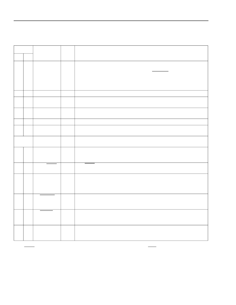
Table 1. Pin Descriptions-Channel 1 and Channel 2
(continued)
* I
u
indicates an internal pull-up.
After RESET is deasserted, the channel is in the default framing mode, as a function of the DS1/CEPT pin.
Asserting this pin low will initially force RDY to a low state.
Pin
Symbol
Type
*
Description
CH1 CH2
11
27
RTIP_RPD
I
Receive Bipolar Tip.
Positive bipolar input data from the receive analog line
isolation transformer.
Receive Positive Rail Data.
Valid when the FRAMER pin is strapped to 0 V.
NRZ serial data latched by the rising edge of RLCK. Data rates:
DS1-1.544 Mbits/s; CEPT-2.048 Mbits/s. Optional single-rail NRZ receive
data latched by the rising edge of RLCK.
Analog 5 V Power Supply. 5 V ± 5%.
Transmit Line Driver Ground Reference.
13
14,
18
15
25
20,
24
23
V
DDA
GRNDX
P
P
TRING
O
Transmit Bipolar Ring.
Negative bipolar output data to the transmit analog
isolation transformer.
Transmit Line Driver 5 V Power Supply.
5 V ± 5%.
Transmit Bipolar Tip.
Positive bipolar output data to the transmit analog
isolation transformer.
5 V Power Supply.
5 V ± 5%.
16
17
22
21
V
DD
X
TTIP
P
O
37, 72,
108, 144
143
V
DD
P
39
LOPLLCK
O
Loss of PLLCK Clock.
This pin is asserted high when the PLLCK clock does
not toggle for a 250 μs interval. This pin is deasserted 250 μs after PLLCK
clock restarts toggling.
DS1/CEPT.
Strap to V
DD
to enable defaults for DS1 operation. Strap to V
SS
to
enable defaults for CEPT operation.
Framer Mode.
Strap to V
DD
to enable integrated LIU and framer operation.
Strap to V
SS
to bypass the LIU section; the receive framer is sourced directly
from the RPD, RND, and RLCK pins while the TPD, TND, and TLCK pins are
driven by the transmit framer.
3-State (Active-Low).
Asserting this pin low forces the channel outputs into a
high-impedance state. Asserting both 3-state pins low forces all outputs into a
high-impedance state.
Reset (Active-Low).
Asserting this pin low resets the channel.
Asserting both RESET pins low resets the entire device including the global
registers.
Transmit Line Interface Positive-Rail Data.
This signal is the transmit
framer positive NRZ output data. Data changes on the rising edge of TLCK.
In the single-rail mode, TPD = transmit framer data.
142
40
DS1/CEPT
I
u
141
41
FRAMER
I
u
140
42
3-STATE
I
u
139
43
RESET
I
u
138
44
TPD
O
相關(guān)PDF資料 |
PDF描述 |
|---|---|
| T7630 | Dual T1/E1 5.0 V Short-Haul Terminator (Terminator-II)(雙 T1/E1 5.0V短距離通信終端器) |
| T8100A | H.100/H.110 Interface and Time-Slot Interchangers |
| T8102A | H.100/H.110 Interface and Time-Slot Interchangers |
| T8105A | H.100/H.110 Interface and Time-Slot Interchangers |
| T8100 | H.100/H.110 Interface and Time-Slot Interchanger |
相關(guān)代理商/技術(shù)參數(shù) |
參數(shù)描述 |
|---|---|
| T7630426 | 制造商:COOPER INDUSTRIES 功能描述:CC ACCESYS / #2450 3/8 Spring Snap Link Stainless Steel UPC Tagged |
| T-7630-TL2-DB | 制造商:Legerity 功能描述:5V DUAL T1/E1 SHORT-HAUL TERMINATOR |
| T7633 | 制造商:AGERE 制造商全稱:AGERE 功能描述:Dual T1/E1 3.3 V Short-Haul Terminator |
| T7645036 | 功能描述:手工工具 Campbell Snap Link #2450, 7/16", Steel RoHS:否 制造商:Molex 產(chǎn)品:Extraction Tools 類型: 描述/功能:Extraction tool |
| T7645106 | 制造商:COOPER INDUSTRIES 功能描述:CC ACCESYS / #7350 1/8 Quick Link Steel Zinc Plated UPC Tagged |
發(fā)布緊急采購,3分鐘左右您將得到回復(fù)。