- 您現(xiàn)在的位置:買賣IC網(wǎng) > PDF目錄371179 > T7630 T7630 Dual T1/E1 5.0 V Short-Haul Terminator (Terminator-II) PDF資料下載
參數(shù)資料
| 型號: | T7630 |
| 英文描述: | T7630 Dual T1/E1 5.0 V Short-Haul Terminator (Terminator-II) |
| 中文描述: | T7630雙T1/E1的5.0V的短途終結(jié)者(終結(jié)者-Ⅱ) |
| 文件頁數(shù): | 57/210頁 |
| 文件大小: | 3075K |
| 代理商: | T7630 |
第1頁第2頁第3頁第4頁第5頁第6頁第7頁第8頁第9頁第10頁第11頁第12頁第13頁第14頁第15頁第16頁第17頁第18頁第19頁第20頁第21頁第22頁第23頁第24頁第25頁第26頁第27頁第28頁第29頁第30頁第31頁第32頁第33頁第34頁第35頁第36頁第37頁第38頁第39頁第40頁第41頁第42頁第43頁第44頁第45頁第46頁第47頁第48頁第49頁第50頁第51頁第52頁第53頁第54頁第55頁第56頁當前第57頁第58頁第59頁第60頁第61頁第62頁第63頁第64頁第65頁第66頁第67頁第68頁第69頁第70頁第71頁第72頁第73頁第74頁第75頁第76頁第77頁第78頁第79頁第80頁第81頁第82頁第83頁第84頁第85頁第86頁第87頁第88頁第89頁第90頁第91頁第92頁第93頁第94頁第95頁第96頁第97頁第98頁第99頁第100頁第101頁第102頁第103頁第104頁第105頁第106頁第107頁第108頁第109頁第110頁第111頁第112頁第113頁第114頁第115頁第116頁第117頁第118頁第119頁第120頁第121頁第122頁第123頁第124頁第125頁第126頁第127頁第128頁第129頁第130頁第131頁第132頁第133頁第134頁第135頁第136頁第137頁第138頁第139頁第140頁第141頁第142頁第143頁第144頁第145頁第146頁第147頁第148頁第149頁第150頁第151頁第152頁第153頁第154頁第155頁第156頁第157頁第158頁第159頁第160頁第161頁第162頁第163頁第164頁第165頁第166頁第167頁第168頁第169頁第170頁第171頁第172頁第173頁第174頁第175頁第176頁第177頁第178頁第179頁第180頁第181頁第182頁第183頁第184頁第185頁第186頁第187頁第188頁第189頁第190頁第191頁第192頁第193頁第194頁第195頁第196頁第197頁第198頁第199頁第200頁第201頁第202頁第203頁第204頁第205頁第206頁第207頁第208頁第209頁第210頁

Lucent Technologies Inc.
Lucent Technologies Inc.
57
Preliminary Data Sheet
October 2000
T7630 Dual T1/E1 5.0 V Short-Haul Terminator (Terminator-II)
Frame Formats
(continued)
Cyclic redundancy checking is performed over the entire ESF data payload (4,608 data bits, with all 24 framing bits
(F
E
, D
L
, CRC-6) set to one during calculations). The CRC-6 bits transmitted in ESF will be determined as follows:
I
The check bits, c1 through c6, contained in ESF(n+ 1) will always be those associated with the contents of
ESF(n), the immediately preceding ESF. When there is no ESF immediately preceding, the check bits may be
assigned any value.
I
For the purpose of CRC-6 calculation only, every F bit in ESF(n) is set to 1. ESF(n) is altered in no other way.
I
The resulting 4632 bits of ESF(n) are used, in order of occurrence, to construct a polynomial in x such that the
first bit of ESF(n) is the coefficient of the term x
4631
and the last bit of ESF(n) is the coefficient of the term x
0
.
I
The polynomial is multiplied by the factor x
6
, and the result is divided, modulo 2, by the generator polynomial x
6
+ x + 1. The coefficients of the remainder polynomial are used, in order of occurrence, as the ordered set of
check bits, c1 through c6, that are transmitted in ESF(n+ 1). The ordering is such that the coefficient of the term
x
5
in the remainder polynomial is check bit c1 and the coefficient of the term x
0
in the remainder polynomial is
check bit c6.
The ESF remote frame alarm consists of a repeated eight ones followed by eight zeros transmitted in the data link
position of the framing bits.
T1 Loss of Frame Alignment (LFA)
Loss of frame alignment condition for the superframe or the extended superframe formats is caused by the inability
of the receive framer to maintain the proper sequence of frame bits. The number of errored framing bits required to
detect a loss of frame alignment is given is Table 26.
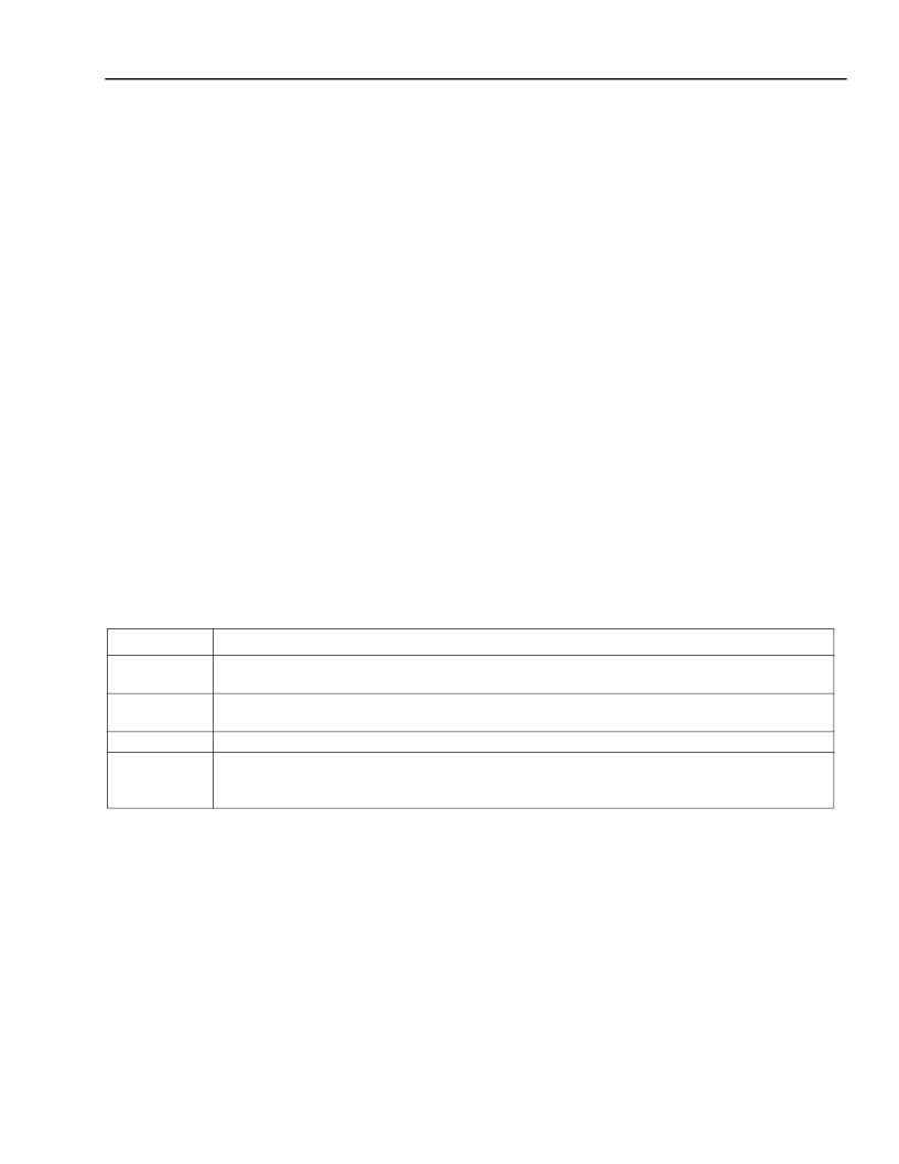
Table 26. T1 Loss of Frame Alignment Criteria
The receive framer indicates the loss of frame and superframe conditions by setting the LFA and LSFA bits
(FRM_SR1 bit 0 and bit 1), respectively, in the status registers for the duration of the conditions. The local system
may give indication of its LFA state to the remote end by transmitting a remote frame alarm (RFA). In addition, in
the LFA state, the system may transmit an alarm indication signal (AIS) to the system interface.
Format
Number of Errored Framing Bits That Will Cause a Loss of Frame Alignment Condition
2 errored frame bits (F
T
or F
S
) out of 4 consecutive frame bits if FRM_PR10 bit 2 = 1.
2 errored F
T
bits out of 4 consecutive F
T
bits if PRM_PR10 bit 2 = 0.
2 errored frame bits (F
T
or F
S
) out of 4 consecutive frame bits if FRM_PR10 bit 2 = 1.
2 errored F
T
bits out of 4 consecutive F
T
bits if FRM_PR10 bit 2 = 0.
3 errored frame bits (F
T
or F
S
) or channel 24 FAS pattern out of 12 consecutive frame bits.
2 errored F
E
bits out of 4 consecutive F
E
bits or optionally 320 or more CRC-6 errored check-
sums within a one second interval if loss of frame alignment due to excessive CRC-6 errors is
enabled in FRM_PR9.
D4
SLC-96
DDS: Frame
ESF
相關PDF資料 |
PDF描述 |
|---|---|
| T7630 | Dual T1/E1 5.0 V Short-Haul Terminator (Terminator-II)(雙 T1/E1 5.0V短距離通信終端器) |
| T8100A | H.100/H.110 Interface and Time-Slot Interchangers |
| T8102A | H.100/H.110 Interface and Time-Slot Interchangers |
| T8105A | H.100/H.110 Interface and Time-Slot Interchangers |
| T8100 | H.100/H.110 Interface and Time-Slot Interchanger |
相關代理商/技術參數(shù) |
參數(shù)描述 |
|---|---|
| T7630426 | 制造商:COOPER INDUSTRIES 功能描述:CC ACCESYS / #2450 3/8 Spring Snap Link Stainless Steel UPC Tagged |
| T-7630-TL2-DB | 制造商:Legerity 功能描述:5V DUAL T1/E1 SHORT-HAUL TERMINATOR |
| T7633 | 制造商:AGERE 制造商全稱:AGERE 功能描述:Dual T1/E1 3.3 V Short-Haul Terminator |
| T7645036 | 功能描述:手工工具 Campbell Snap Link #2450, 7/16", Steel RoHS:否 制造商:Molex 產(chǎn)品:Extraction Tools 類型: 描述/功能:Extraction tool |
| T7645106 | 制造商:COOPER INDUSTRIES 功能描述:CC ACCESYS / #7350 1/8 Quick Link Steel Zinc Plated UPC Tagged |
發(fā)布緊急采購,3分鐘左右您將得到回復。