- 您現(xiàn)在的位置:買賣IC網(wǎng) > PDF目錄361647 > V363EPC-50 Controller Miscellaneous - Datasheet Reference PDF資料下載
參數(shù)資料
| 型號: | V363EPC-50 |
| 英文描述: | Controller Miscellaneous - Datasheet Reference |
| 中文描述: | 控制器雜項-數(shù)據(jù)表參考 |
| 文件頁數(shù): | 100/190頁 |
| 文件大小: | 1105K |
| 代理商: | V363EPC-50 |
第1頁第2頁第3頁第4頁第5頁第6頁第7頁第8頁第9頁第10頁第11頁第12頁第13頁第14頁第15頁第16頁第17頁第18頁第19頁第20頁第21頁第22頁第23頁第24頁第25頁第26頁第27頁第28頁第29頁第30頁第31頁第32頁第33頁第34頁第35頁第36頁第37頁第38頁第39頁第40頁第41頁第42頁第43頁第44頁第45頁第46頁第47頁第48頁第49頁第50頁第51頁第52頁第53頁第54頁第55頁第56頁第57頁第58頁第59頁第60頁第61頁第62頁第63頁第64頁第65頁第66頁第67頁第68頁第69頁第70頁第71頁第72頁第73頁第74頁第75頁第76頁第77頁第78頁第79頁第80頁第81頁第82頁第83頁第84頁第85頁第86頁第87頁第88頁第89頁第90頁第91頁第92頁第93頁第94頁第95頁第96頁第97頁第98頁第99頁當前第100頁第101頁第102頁第103頁第104頁第105頁第106頁第107頁第108頁第109頁第110頁第111頁第112頁第113頁第114頁第115頁第116頁第117頁第118頁第119頁第120頁第121頁第122頁第123頁第124頁第125頁第126頁第127頁第128頁第129頁第130頁第131頁第132頁第133頁第134頁第135頁第136頁第137頁第138頁第139頁第140頁第141頁第142頁第143頁第144頁第145頁第146頁第147頁第148頁第149頁第150頁第151頁第152頁第153頁第154頁第155頁第156頁第157頁第158頁第159頁第160頁第161頁第162頁第163頁第164頁第165頁第166頁第167頁第168頁第169頁第170頁第171頁第172頁第173頁第174頁第175頁第176頁第177頁第178頁第179頁第180頁第181頁第182頁第183頁第184頁第185頁第186頁第187頁第188頁第189頁第190頁

PCI Configuration
Configuration as a System Host Bridge
90
EPC User
’
s Manual Revision 1.05
Copyright 1997-2000, V3 Semiconductor Inc.
9.1.3
Generating Configuration Reads and Writes
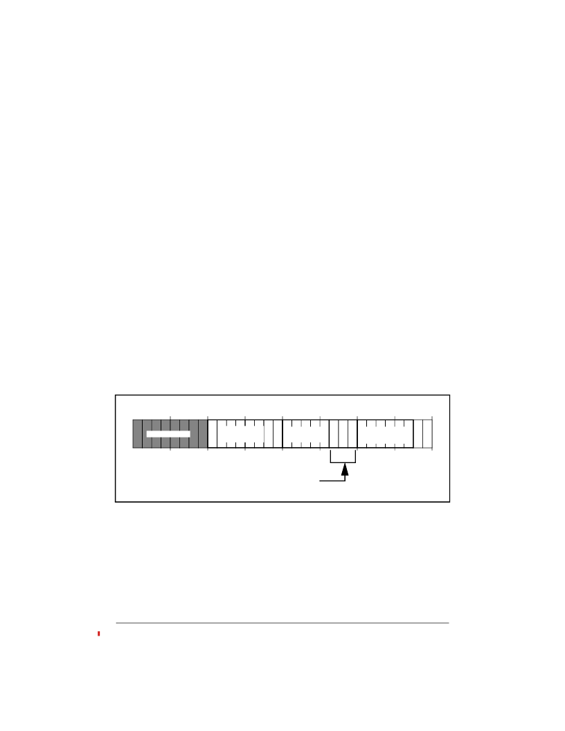
The address placed on the bus during configuration cycles is actually encoded information
as shown in Figure 47. The EPC does not automatically generate this encoding, it is
completely under software control. The configuration address encoding is programmed as
follows:
Setup one of the Local-to-PCI apertures as 16 megabytes in length. This forces the
address translation logic to pass the lower 24 bits of the address through to the PCI
bus without translation. The lower 24 bits of the address are the encoded
configuration information. The base address in Local memory for this aperture may
be placed on any 16Mbyte boundary.
Setup the address translation for the above aperture to translate accesses to
0000.0000H. Since the aperture is setup for 16Mbytes, this has the effect of setting
A[31:24] to zeros. Set the TYPE field for the Local-to-PCI aperture to
“
Configuration
Reads/Writes
”
.
Create a 24-bit value that encodes the configuration address information. Add the
base address of the Local-to-PCI aperture to this encoded information.
Perform a read (or write) to the above address in local space. This will be translated
to a configuration read (or write) in PCI space.
In the above example, it is assumed that the IDSEL lines are set appropriately by the user
’
s
system hardware and software.
Figure 47: Encoded Configuration Address Information
9.1.4
Using Configuration Information
The following information is usually determined during configuration:
What PCI devices are present in the system and what type of devices they are
What resources are necessary for each device in terms of memory, I/O, and
interrupts
What capabilities each of the devices has (i.e. Fast Back-to-Back capable)
0
4
8
12
16
20
24
28
0 0
REGISTER
NUMBER
DEVICE
NUMBER
BUS
NUMBER
FUNCTION
NUMBER
RESERVED
相關(guān)PDF資料 |
PDF描述 |
|---|---|
| V363ME01-LF | VOLTAGE CONTROLLED OSCILLATOR |
| V370PDC-66 | DRAM Controller |
| V375A12M300A2L | Analog IC |
| V375A12M300A3 | Analog IC |
| V375A12M300A3L | Analog IC |
相關(guān)代理商/技術(shù)參數(shù) |
參數(shù)描述 |
|---|---|
| V363EPC-50LP | 制造商:Rochester Electronics LLC 功能描述: 制造商:QuickLogic Corporation 功能描述: |
| V363EPC-50LPN | 制造商:Rochester Electronics LLC 功能描述: 制造商:QuickLogic Corporation 功能描述: |
| V363ME01-LF | 制造商:ZCOMM 制造商全稱:ZCOMM 功能描述:Voltage-Controlled Oscillator Surface Mount Module |
| V363ME01-LF_10 | 制造商:ZCOMM 制造商全稱:ZCOMM 功能描述:Voltage-Controlled Oscillator Surface Mount Module |
| V364 | 制造商:VARTA 功能描述: |
發(fā)布緊急采購,3分鐘左右您將得到回復(fù)。