- 您現(xiàn)在的位置:買賣IC網(wǎng) > PDF目錄295065 > AM79C965KCW (ADVANCED MICRO DEVICES INC) 3 CHANNEL(S), LOCAL AREA NETWORK CONTROLLER, PQFP16 PDF資料下載
參數(shù)資料
| 型號: | AM79C965KCW |
| 廠商: | ADVANCED MICRO DEVICES INC |
| 元件分類: | 微控制器/微處理器 |
| 英文描述: | 3 CHANNEL(S), LOCAL AREA NETWORK CONTROLLER, PQFP16 |
| 封裝: | PLASTIC, QFP-160 |
| 文件頁數(shù): | 124/220頁 |
| 文件大小: | 1197K |
| 代理商: | AM79C965KCW |
第1頁第2頁第3頁第4頁第5頁第6頁第7頁第8頁第9頁第10頁第11頁第12頁第13頁第14頁第15頁第16頁第17頁第18頁第19頁第20頁第21頁第22頁第23頁第24頁第25頁第26頁第27頁第28頁第29頁第30頁第31頁第32頁第33頁第34頁第35頁第36頁第37頁第38頁第39頁第40頁第41頁第42頁第43頁第44頁第45頁第46頁第47頁第48頁第49頁第50頁第51頁第52頁第53頁第54頁第55頁第56頁第57頁第58頁第59頁第60頁第61頁第62頁第63頁第64頁第65頁第66頁第67頁第68頁第69頁第70頁第71頁第72頁第73頁第74頁第75頁第76頁第77頁第78頁第79頁第80頁第81頁第82頁第83頁第84頁第85頁第86頁第87頁第88頁第89頁第90頁第91頁第92頁第93頁第94頁第95頁第96頁第97頁第98頁第99頁第100頁第101頁第102頁第103頁第104頁第105頁第106頁第107頁第108頁第109頁第110頁第111頁第112頁第113頁第114頁第115頁第116頁第117頁第118頁第119頁第120頁第121頁第122頁第123頁當前第124頁第125頁第126頁第127頁第128頁第129頁第130頁第131頁第132頁第133頁第134頁第135頁第136頁第137頁第138頁第139頁第140頁第141頁第142頁第143頁第144頁第145頁第146頁第147頁第148頁第149頁第150頁第151頁第152頁第153頁第154頁第155頁第156頁第157頁第158頁第159頁第160頁第161頁第162頁第163頁第164頁第165頁第166頁第167頁第168頁第169頁第170頁第171頁第172頁第173頁第174頁第175頁第176頁第177頁第178頁第179頁第180頁第181頁第182頁第183頁第184頁第185頁第186頁第187頁第188頁第189頁第190頁第191頁第192頁第193頁第194頁第195頁第196頁第197頁第198頁第199頁第200頁第201頁第202頁第203頁第204頁第205頁第206頁第207頁第208頁第209頁第210頁第211頁第212頁第213頁第214頁第215頁第216頁第217頁第218頁第219頁第220頁
P R E L I M I N A R Y
AMD
21
Am79C965
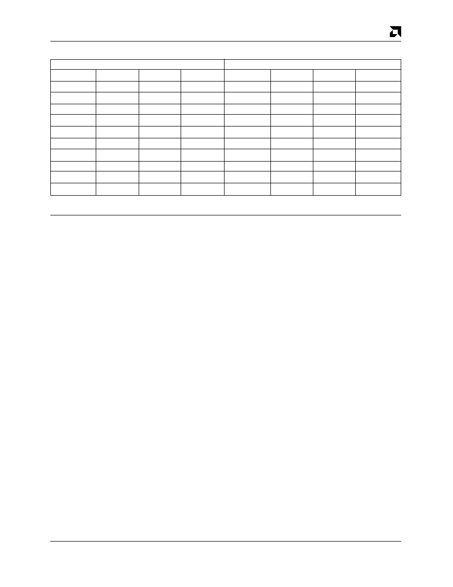
Table 8. Data Transfer Sequence from 32-Bit Wide to 16-Bit Wide
BE3
BE2
BE1
BE0
BE3
BE2
BE1
BE0
1
110
NR
1
100
NR
1
000
1
0
1
0
000
0
1
101
NR
1
001
1
0
1
0
001
0
1
011
NR
0
011
NR
0
111
NR
Next with LBS16
Current Access
NR = No second access Required for these cases
During accesses in which PCnet-32 controller is acting
as the VL-Bus target device, the
LBS16 signal will not be
driven. In this case, it is expected that the VL-Bus
required pull-up device will bring the
LBS16 signal to an
inactive level and the PCnet-32 controller will be seen by
the VL-Bus master as a 32-bit peripheral.
LCLK
Local Clock
Input
LCLK is a 1x clock that follows the same phase as a
486-type CPU clock. LCLK is always driven by the sys-
tem logic or the VL-Bus controller to all VL-Bus masters
and targets. The rising edge of the clock signifies the
change of CPU states, and hence, the change of
PCnet-32 controller states.
LDEV
Local Device
Output
LDEV is driven by the PCnet-32 controller when it recog-
nizes an access to PCnet-32 controller I/O space. Such
recognition is dependent upon a valid sampled
ADS
strobe plus valid M/
IO, D/C and ADR31–ADR5 values.
LEADS
Local External Address Strobe
Output
During VL-Bus master write and read accesses the
LEADS pin will be asserted on every T1 cycle as is
specified in the VESA VL-Bus specification, regardless
of the settings of the GCIC bit of BCR18 and the CLL bits
of BCR18.
LGNT
Local Bus Grant
Input
When
LGNT is asserted and LREQ is being asserted by
the PCnet-32 controller, the PCnet-32 controller as-
sumes ownership of the VL bus.
Note that this pin changes polarity when Local Bus
mode has been selected (see pin description of HLDA in
486 Local Bus Interface section).
LGNTO
Local Grant Out
Output
This signal is multiplexed with the TCK pin, and is avail-
able only when the Multi-Interrupt mode has been se-
lected with the JTAGSEL pin.
An additional local bus master may daisy-chain its
LGNT signal through the PCnet-32 controller LGNTO
pin. The PCnet-32 controller will deliver a
LGNTO signal
to the additional local bus master whenever the
PCnet-32 controller receives a
LGNT from the arbitra-
tion logic, but is not simultaneously requesting the bus
internally. The second local bus master must connect its
LREQ output to the LREQI input of the PCnet-32 con-
troller in order to complete the local bus daisy-chain
arbitration control.
When
SLEEP is not asserted, daisy chain arbitration
signals that pass through the PCnet-32 controller will
experience a one-clock delay from input to output (i.e.
LREQI to LREQ and LGNT to LGNTO).
While
SLEEP is asserted (either in snooze mode or
coma mode), if the PCnet-32 controller is configured for
a daisy chain (
LREQI and LGNTO signals have been
selected with the JTAGSEL pin), then the system arbi-
tration signal
LGNT will be passed directly to the daisy-
chain signal
LGNTO without experiencing a one-clock
delay. However, some combinatorial delay will be intro-
duced in this path.
Note that this pin changes polarity when Local Bus
mode has been selected (see pin description of HLDAO
in 486 Local Bus Interface section).
LRDY
Local Ready
Output
LRDY functions as an output from the PCnet-32 control-
ler during PCnet-32 controller slave cycles. During
PCnet-32 controller slave read cycles,
LRDY is as-
serted to indicate that valid data has been presented on
相關PDF資料 |
PDF描述 |
|---|---|
| AM80A-024L-120F18 | 1-OUTPUT 240 W DC-DC REG PWR SUPPLY MODULE |
| AJ80A-024L-033F50 | 1-OUTPUT 240 W DC-DC REG PWR SUPPLY MODULE |
| AM93LC66S | 4096-bits Serial Electrically Erasable PROM |
| AM93LC66SA | 4096-bits Serial Electrically Erasable PROM |
| AM93LC66VN | 4096-bits Serial Electrically Erasable PROM |
相關代理商/技術參數(shù) |
參數(shù)描述 |
|---|---|
| AM79C970 | 制造商:AMD 制造商全稱:Advanced Micro Devices 功能描述:PCnetTM-PCI Single-Chip Ethernet Controller for PCI Local Bus |
| AM79C970A | 制造商:AMD 制造商全稱:Advanced Micro Devices 功能描述:PCnet-PCI II Single-Chip Full-Duplex Ethernet Controller for PCI Local Bus Product |
| AM79C970AKC | 制造商:AMD 制造商全稱:Advanced Micro Devices 功能描述:PCnet-PCI II Single-Chip Full-Duplex Ethernet Controller for PCI Local Bus Product |
| AM79C970AKC\\W | 制造商:Rochester Electronics LLC 功能描述:- Bulk 制造商:Advanced Micro Devices 功能描述: |
發(fā)布緊急采購,3分鐘左右您將得到回復。