- 您現(xiàn)在的位置:買賣IC網(wǎng) > PDF目錄295065 > AM79C965KCW (ADVANCED MICRO DEVICES INC) 3 CHANNEL(S), LOCAL AREA NETWORK CONTROLLER, PQFP16 PDF資料下載
參數(shù)資料
| 型號: | AM79C965KCW |
| 廠商: | ADVANCED MICRO DEVICES INC |
| 元件分類: | 微控制器/微處理器 |
| 英文描述: | 3 CHANNEL(S), LOCAL AREA NETWORK CONTROLLER, PQFP16 |
| 封裝: | PLASTIC, QFP-160 |
| 文件頁數(shù): | 200/220頁 |
| 文件大小: | 1197K |
| 代理商: | AM79C965KCW |
第1頁第2頁第3頁第4頁第5頁第6頁第7頁第8頁第9頁第10頁第11頁第12頁第13頁第14頁第15頁第16頁第17頁第18頁第19頁第20頁第21頁第22頁第23頁第24頁第25頁第26頁第27頁第28頁第29頁第30頁第31頁第32頁第33頁第34頁第35頁第36頁第37頁第38頁第39頁第40頁第41頁第42頁第43頁第44頁第45頁第46頁第47頁第48頁第49頁第50頁第51頁第52頁第53頁第54頁第55頁第56頁第57頁第58頁第59頁第60頁第61頁第62頁第63頁第64頁第65頁第66頁第67頁第68頁第69頁第70頁第71頁第72頁第73頁第74頁第75頁第76頁第77頁第78頁第79頁第80頁第81頁第82頁第83頁第84頁第85頁第86頁第87頁第88頁第89頁第90頁第91頁第92頁第93頁第94頁第95頁第96頁第97頁第98頁第99頁第100頁第101頁第102頁第103頁第104頁第105頁第106頁第107頁第108頁第109頁第110頁第111頁第112頁第113頁第114頁第115頁第116頁第117頁第118頁第119頁第120頁第121頁第122頁第123頁第124頁第125頁第126頁第127頁第128頁第129頁第130頁第131頁第132頁第133頁第134頁第135頁第136頁第137頁第138頁第139頁第140頁第141頁第142頁第143頁第144頁第145頁第146頁第147頁第148頁第149頁第150頁第151頁第152頁第153頁第154頁第155頁第156頁第157頁第158頁第159頁第160頁第161頁第162頁第163頁第164頁第165頁第166頁第167頁第168頁第169頁第170頁第171頁第172頁第173頁第174頁第175頁第176頁第177頁第178頁第179頁第180頁第181頁第182頁第183頁第184頁第185頁第186頁第187頁第188頁第189頁第190頁第191頁第192頁第193頁第194頁第195頁第196頁第197頁第198頁第199頁當(dāng)前第200頁第201頁第202頁第203頁第204頁第205頁第206頁第207頁第208頁第209頁第210頁第211頁第212頁第213頁第214頁第215頁第216頁第217頁第218頁第219頁第220頁
AMD
P R E L I M I N A R Y
80
Am79C965
signal, since the internal Buffer Management Unit clock
is a divide-by-two version of the BCLK signal.
The PCnet-32 controller
RDY and RDYRTN signals
may be wired together. This allows the PCnet-32
controller to operate within a system that has a single
READY signal.
The
LDEV signal is generated in response to a valid
PCnet-32 controller I/O address on the bus together
with a valid
ADS signal. LDEV is generated in an asyn-
chronous manner by the PCnet-32 controller. See the
parameter listings for delay values of the
LDEV signal.
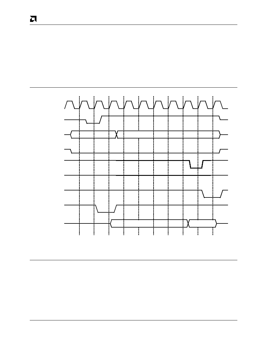
RDY, BRDY and D[31:0] are never driven until the sec-
ond T2 state of a slave access. Before that time, it is
expected that a system pull-up device is holding the
RDY and BRDY signals in a deasserted state.
The
RDY and BRDY signals are always driven high for
one half BCLK cycle immediately following the BCLK
period during which
RDY was driven asserted. Then the
RDY and BRDY signals are floated. This behavior is
performed regardless of the PCnet-32 controller mode
setting. See Figure 25.
18219B-28
ADS
Ti
BCLK
T1
T2
ADDRESS,
BE0-BE3,
M/
IO,
D/
C
RDY
W/
R
BRDY
D0-D31
T2
T2x
Ti
From
PCnet-32
LDEV
Valid
Not Valid
RDYRTN
Figure 25. Slave RDY Timing
VESA VL-Bus Mode Timing
VESA VL-Bus mode functional timing is essentially
identical to the timing of the Am486 32-bit mode, except
that the bus request and bus acknowledge signals have
inverted senses from those shown in the previous timing
diagrams and the AHOLD signal does not exist while the
PCnet-32 controller is programmed for VL-Bus mode. In
addition, dynamic bus sizing is supported in VESA VL-
Bus mode, through the use of the
LBS16 signal. The
following section describes possible
LBS16 interactions
while programmed for the VESA VL-Bus mode of
operation. Other differences exist between VL-Bus
mode and Am486 mode, but these other differences are
not directly related to the master or slave cycle timings.
Effect of LBS16 (VL-Bus mode only)
Dynamic bus sizing is recognized by the PCnet-32 con-
troller while operating in the VL-Bus mode. The
LBS16
signal is used to indicate to the PCnet-32 controller
whether the VL-Bus target is a 16-bit or 32-bit periph-
eral. When the target device indicates that it is 16 bits in
width by asserting the
LBS16 signal at least one LCLK
相關(guān)PDF資料 |
PDF描述 |
|---|---|
| AM80A-024L-120F18 | 1-OUTPUT 240 W DC-DC REG PWR SUPPLY MODULE |
| AJ80A-024L-033F50 | 1-OUTPUT 240 W DC-DC REG PWR SUPPLY MODULE |
| AM93LC66S | 4096-bits Serial Electrically Erasable PROM |
| AM93LC66SA | 4096-bits Serial Electrically Erasable PROM |
| AM93LC66VN | 4096-bits Serial Electrically Erasable PROM |
相關(guān)代理商/技術(shù)參數(shù) |
參數(shù)描述 |
|---|---|
| AM79C970 | 制造商:AMD 制造商全稱:Advanced Micro Devices 功能描述:PCnetTM-PCI Single-Chip Ethernet Controller for PCI Local Bus |
| AM79C970A | 制造商:AMD 制造商全稱:Advanced Micro Devices 功能描述:PCnet-PCI II Single-Chip Full-Duplex Ethernet Controller for PCI Local Bus Product |
| AM79C970AKC | 制造商:AMD 制造商全稱:Advanced Micro Devices 功能描述:PCnet-PCI II Single-Chip Full-Duplex Ethernet Controller for PCI Local Bus Product |
| AM79C970AKC\\W | 制造商:Rochester Electronics LLC 功能描述:- Bulk 制造商:Advanced Micro Devices 功能描述: |
發(fā)布緊急采購,3分鐘左右您將得到回復(fù)。