- 您現在的位置:買賣IC網 > PDF目錄371179 > T8302 T8302 Internet Protocol Telephone Advanced RISC Machine (ARM) Ethernet QoS Using IEEE 802.1q PDF資料下載
參數資料
| 型號: | T8302 |
| 英文描述: | T8302 Internet Protocol Telephone Advanced RISC Machine (ARM) Ethernet QoS Using IEEE 802.1q |
| 中文描述: | T8302因特網協(xié)議電話高級RISC機(ARM)的以太網使用IEEE 802.1q的服務質量 |
| 文件頁數: | 62/248頁 |
| 文件大小: | 7321K |
| 代理商: | T8302 |
第1頁第2頁第3頁第4頁第5頁第6頁第7頁第8頁第9頁第10頁第11頁第12頁第13頁第14頁第15頁第16頁第17頁第18頁第19頁第20頁第21頁第22頁第23頁第24頁第25頁第26頁第27頁第28頁第29頁第30頁第31頁第32頁第33頁第34頁第35頁第36頁第37頁第38頁第39頁第40頁第41頁第42頁第43頁第44頁第45頁第46頁第47頁第48頁第49頁第50頁第51頁第52頁第53頁第54頁第55頁第56頁第57頁第58頁第59頁第60頁第61頁當前第62頁第63頁第64頁第65頁第66頁第67頁第68頁第69頁第70頁第71頁第72頁第73頁第74頁第75頁第76頁第77頁第78頁第79頁第80頁第81頁第82頁第83頁第84頁第85頁第86頁第87頁第88頁第89頁第90頁第91頁第92頁第93頁第94頁第95頁第96頁第97頁第98頁第99頁第100頁第101頁第102頁第103頁第104頁第105頁第106頁第107頁第108頁第109頁第110頁第111頁第112頁第113頁第114頁第115頁第116頁第117頁第118頁第119頁第120頁第121頁第122頁第123頁第124頁第125頁第126頁第127頁第128頁第129頁第130頁第131頁第132頁第133頁第134頁第135頁第136頁第137頁第138頁第139頁第140頁第141頁第142頁第143頁第144頁第145頁第146頁第147頁第148頁第149頁第150頁第151頁第152頁第153頁第154頁第155頁第156頁第157頁第158頁第159頁第160頁第161頁第162頁第163頁第164頁第165頁第166頁第167頁第168頁第169頁第170頁第171頁第172頁第173頁第174頁第175頁第176頁第177頁第178頁第179頁第180頁第181頁第182頁第183頁第184頁第185頁第186頁第187頁第188頁第189頁第190頁第191頁第192頁第193頁第194頁第195頁第196頁第197頁第198頁第199頁第200頁第201頁第202頁第203頁第204頁第205頁第206頁第207頁第208頁第209頁第210頁第211頁第212頁第213頁第214頁第215頁第216頁第217頁第218頁第219頁第220頁第221頁第222頁第223頁第224頁第225頁第226頁第227頁第228頁第229頁第230頁第231頁第232頁第233頁第234頁第235頁第236頁第237頁第238頁第239頁第240頁第241頁第242頁第243頁第244頁第245頁第246頁第247頁第248頁
60
Agere Systems Inc.
T8302 Internet Protocol Telephone
Advanced RISC Machine (
ARM
)
Data Sheet
July 2001
6 Programmable Direct Memory Access (DMA) Controller
(continued)
There is a single transfer option available in mode 2 as follows:
I
The DMA will transfer until the transfer count, programmed through the
DMA preload transfer count register
(see Table 40 on page 65)
, is reached.
I
Mode 2 does not support circular buffer mode.
6.1.4.1 Software-Triggered DMA Mode
There is a software triggered DMA mode that does not use the DMA ready signal from the peripheral. This mode is
selected by setting the software trigger enable bit (
SDRQ_E
) in the
DMA control register
(see Table 36 on page
62)
. When the user is sure the number of words set up to be transferred is available in the peripheral's buffer, the
DMA is triggered by setting the software trigger DMA request bit (
SDRQ
) in the
DMA control register
. The DMA
ready signal is not monitored in this mode. If the DMA attempts to transfer more data then can be buffered in the
peripheral, data will be lost and questionable results will occur.
Notes:
Data transfers to memory from the DSP2
ARM/ARM
2DSP buffer in the DCC block are much more efficient
in this mode, using the peripheral bus address of the DSP2
ARM/ARM
2DSP buffer, as opposed to using
the memory-to-memory mode (mode 0) and the system bus address of the DSP2
ARM/ARM
2DSP buffer.
The memory write and buffer read can occur at the same time since they are on different busses in the
IPT_
ARM
, instead of the sequential read-then-write, that occur in the memory-to-memory mode.
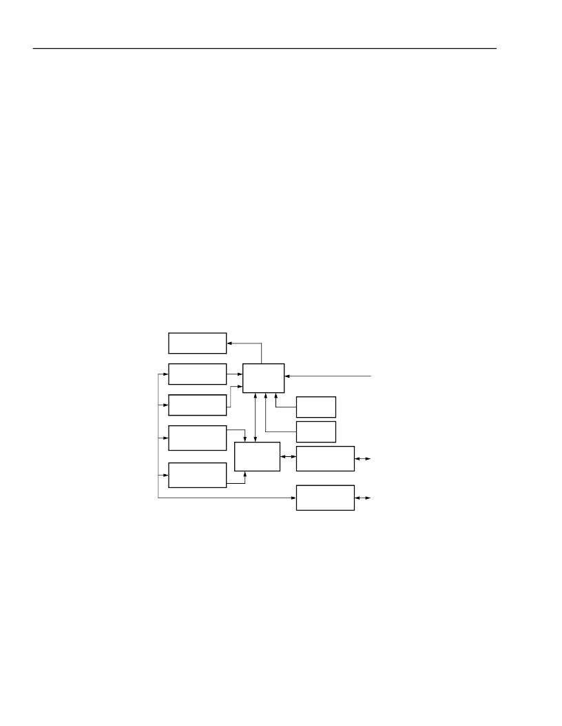
5-8229(F)
Figure 7. DMA Controller Block Diagram 2
INTERRUPT
CONTROLLER
CONTROL
REGISTERS[5:0]
WORD COUNT
REGISTERS[3:0]
DESTINATION
ADDRESS
REGISTERS[3:0]
SOURCE
ADDRESS
REGISTERS[3:0]
CONTROL
LOGIC
ADDRESS
GENERATOR
SSI
INTERFACE
ACC
INTERFACE
AMBA
SYSTEM BUS
INTERFACE
PERIPHERAL
BUS
INTERFACE
IRQ[10:8]
DRC[3:0]
相關PDF資料 |
PDF描述 |
|---|---|
| T8502 | T8502 and T8503 Dual PCM Codecs with Filters |
| T8503 | T8502 and T8503 Dual PCM Codecs with Filters |
| T8531A | T8531A/8532 Multichannel Programmable Codec Chip Set |
| T8531 | T8502 and T8503 Dual PCM Codecs with Filters |
| T8532 | T8502 and T8503 Dual PCM Codecs with Filters |
相關代理商/技術參數 |
參數描述 |
|---|---|
| T8302A | 制造商:MOLEX 制造商全稱:Molex Electronics Ltd. 功能描述:Terminator Die |
| T8302B | 制造商:MOLEX 制造商全稱:Molex Electronics Ltd. 功能描述:Terminator Die |
| T8302F | 制造商:MOLEX 制造商全稱:Molex Electronics Ltd. 功能描述:Terminator Die |
| T8303A | 制造商:MOLEX 制造商全稱:Molex Electronics Ltd. 功能描述:Terminator Die |
| T8303ABNAD | 制造商:Arcolectric 功能描述:1 Pole Miniature push button(with light) |
發(fā)布緊急采購,3分鐘左右您將得到回復。